LDI Intellectual Property.
Not for secondary distribution or replication, in part or entirety.
DIGISONDE-4D
SYSTEM MANUAL
VERSION 1.2.11
SECTION 1 - GENERAL SYSTEM DESCRIPTION 1-33
20 22 24 26 28 30 32 34 36 38 40
0.0
0.2
0.4
0.6
0.8
1.0
1.2
B
A
m
f
I
= 32.3/T
Amplitude, norm.
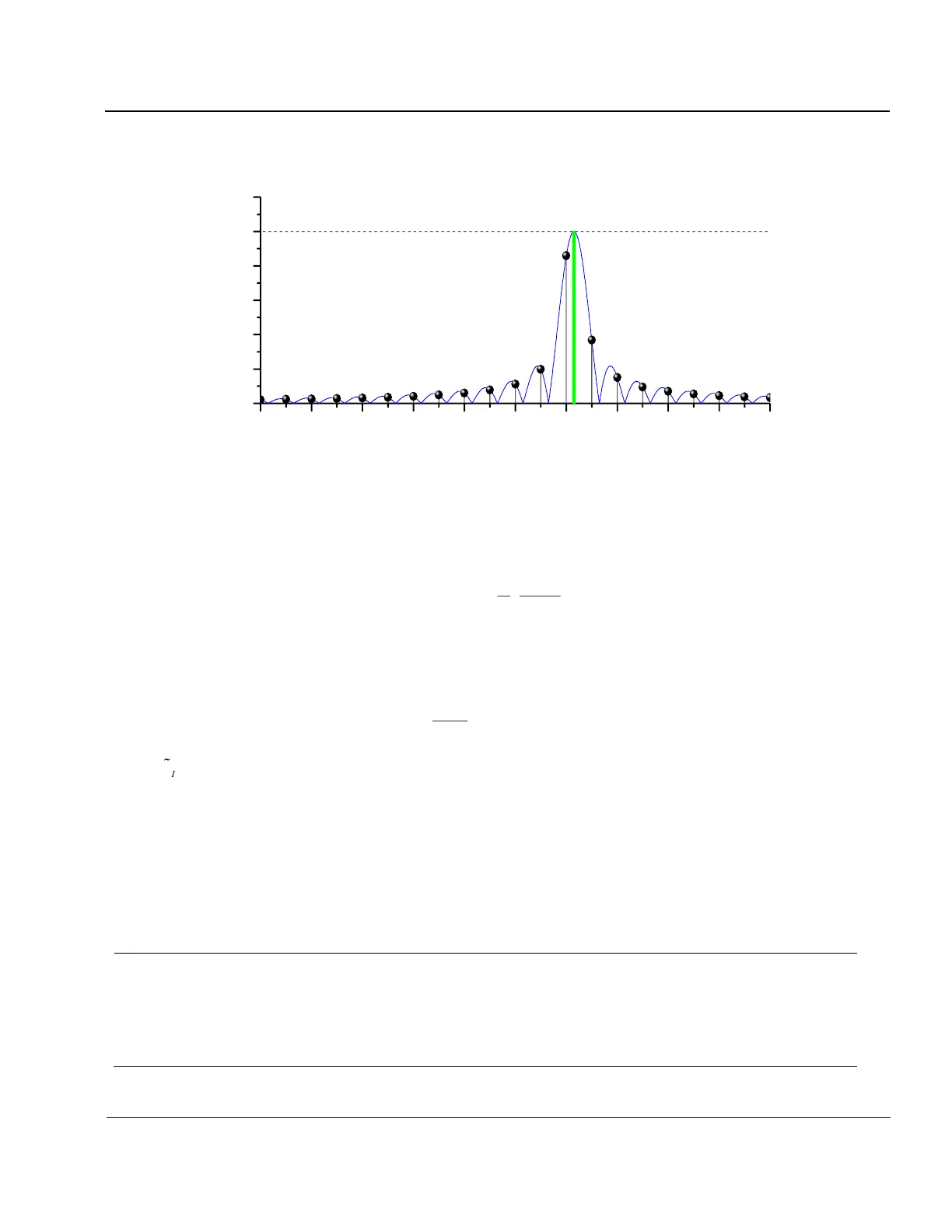
Figure 1-20: Spectrum of a Truncated CW Signal.
1:71. Conventional DFT algorithms calculate the spectral amplitudes of the integer-indexed frequencies that
are multiples of 1/T where T is the coherent integration time. In general, the interferer frequency f
I
will not be a
harmonic of 1/T, i.e., f
I
≠ m/T (Figure 1-20). The frequency f
I
is given by:
where f
A
is the frequency of the stronger of the two strongest spectral components, and A and B are their amplitudes. We
have experimentally verified that this algorithm works reliably. Once the precise frequency is known, a single-line discrete
Fourier transformation determines the amplitude and phase of the interferer:
( )
=
+
=
N
n
InI
nfiS
N
C
0
2exp
~
1
1
~
where
is the complex spectral amplitude,
are the complex signal time samples, and N is the total number of sam-
ples. The inverse transform of (2) gives the precise time domain presentation of the interferer
This function can now simply be subtracted from the input data. The RFIM procedure steps are summarized in Table 1-2.
Table 1-2: RFIM Procedure Steps
Calculate the DFT of the received signal. Find the strongest amplitude A in the spectrum.
If the strongest spike does not qualify as a narrow-band interferer, stop.
Determine the exact frequency of the interferer via Eq. (1).
Do “single line spectral analysis” to determine the exact interferer amplitude and phase and perform the inverse Fouri-
er transformation.
Subtract the interferer signal from the received signal.
If the specified number of iterations is reached, stop. Otherwise, go to Step 1 to determine next strongest interferer