Home
Leica Geosystems
Controller
CS15
Leica Geosystems CS15 User Manual
4
of 1
of 1 rating
1897 pages
Give review
Manual
Specs
To Next Page
To Next Page
To Previous Page
To Previous Page
Loading...
Viva Series,
Coordi
nat
e Sy
ste
ms
162
8.5.2
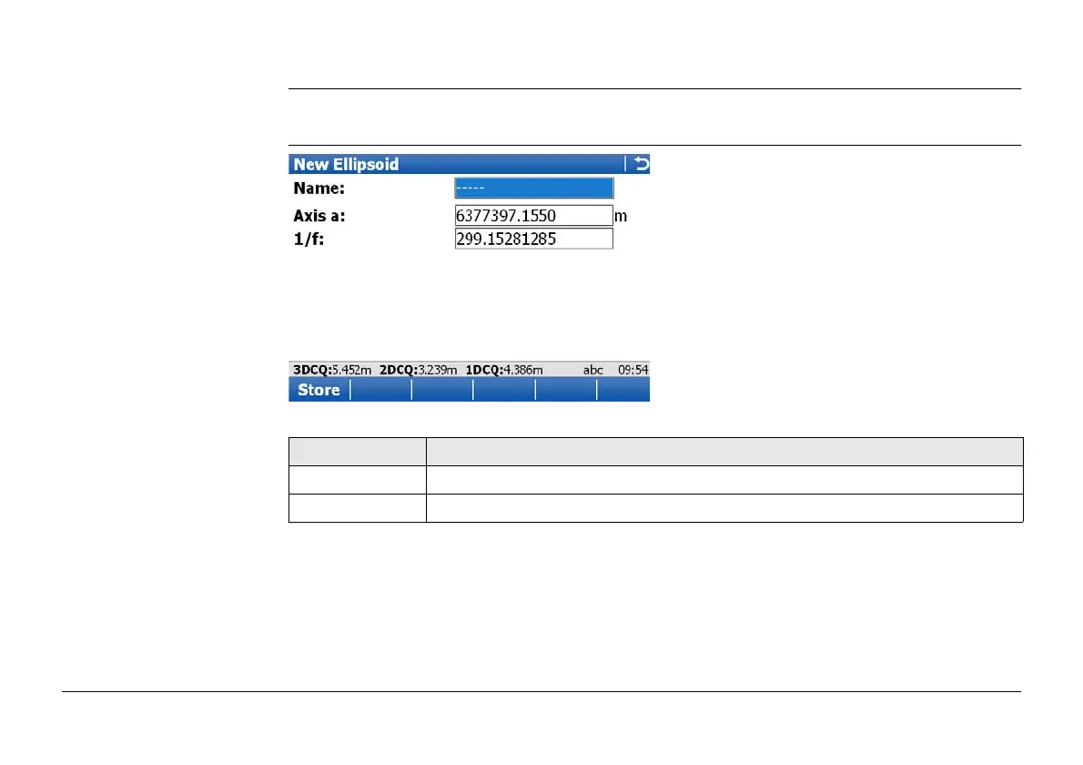
Creating/Editing an Ellipsoid
Access
In
Ellipsoids
, highlight an ellipsoid. A copy of this ellipsoid is taken for further configura-
tions. Press
New..
or
Edit..
.
New Ellipsoid
or
Edit
Ellipsoid
Key
Description
Store
To store the ellipsoid.
Fn
Quit
To exit the screen.
161
163
Table of Contents
Default Chapter
5
Table of Contents
5
1 Configurable Keys
33
Hot Keys
33
Favourites Key
35
2 TPS Settings
37
Leica TPS Favourites
37
Check Point
41
Joystick
44
Turn Instrument to Hz/V
46
Orientation with Compass
48
Using the Digital Camera
50
3 GPS Settings
51
Leica GPS Favourites
51
4 Main Menu
54
Main Menu Functions
54
Go to Work
56
Jobs & Data
58
Instrument
60
User
63
5 Jobs & Data - Jobs
65
Overview
65
Creating a New Job
66
Job Properties and Editing a Job
76
Choosing a Job
84
Managing Job Codes
86
6 Jobs & Data - Data
90
Overview
90
Accessing Data Management
91
Point Management
96
Creating a New Point
96
Editing a Point
101
Mean Page
106
Line/Area Management
113
Overview
113
Creating a New Line/Area
114
Editing a Line/Area
120
Data Log
124
Point Sorting and Filters
126
Sorting and Filters for Points, Lines and Areas
126
Point, Line and Area Code Filter
133
Stakeout Filter
135
7 Codelists
137
Overview
137
Accessing Codelist Management
138
Creating/Editing a Codelist
140
Managing Codes
142
Accessing Codes
142
Creating/Editing a Code
144
Managing Code Groups
147
8 Coordinate Systems
149
Overview
149
Accessing Coordinate System Management
151
Coordinate Systems - Creating and Editing
153
Transformations
156
Accessing Transformation Management
156
Creating/Editing a Transformation
158
Ellipsoids
161
Accessing Ellipsoid Management
161
Creating/Editing an Ellipsoid
162
Projections
164
Accessing Projection Management
164
Creating/Editing a Projection
168
Geoid Models
170
Geoid Models Overview
170
Accessing Geoid Model Management
171
Creating a New Geoid Model from the Data Storage Device / Internal Memory
173
CSCS Models
174
9 Jobs & Data - Import Data
175
Overview
175
Importing Data in ASCII/GSI Format
178
Importing Data for Roadrunner
183
Importing Data in DXF Format
192
10 Jobs & Data - Export & Copy Data
195
Overview
195
Exporting Data from a Job to a Custom ASCII Format
197
Exporting Data in DXF Format
199
Exporting Data in Landxml Format
205
Exporting Data in FBK/RW5/RAW Format
209
Copy Data between Jobs
214
11 Instrument - TPS Settings
217
Measure Mode & Target
217
Measure & Target Settings
217
Targets
221
Creating/Editing a Target
223
Prism Search Settings
225
Atmospheric Corrections
230
Level Bubble & Compensator
234
Offsets & Quality Control
236
Lights / Lights & Accessories
241
12 Instrument - GPS Settings
247
RTK Rover Wizard Overview
247
Creating a New RTK Profile
249
Loading an Existing RTK Profile
250
Editing an Existing RTK Profile
251
Satellite Tracking
253
Antenna Heights
260
Rover Antenna Heights
260
Antennas
262
Creating/Editing an Antenna
264
Quality Control
267
Raw Data Logging
278
13 Antenna Heights
282
Overview
282
Mechanical Reference Planes, MRP
284
Determining Antenna Heights
286
Pillar Setup
286
Tripod Setup
291
Pole Setup
293
Smartstation Setup
295
14 Instrument Connections - GPS Connection Wizard
297
Starting the GPS Connection Wizard
297
Connection to GS10/GS15/GS08/GS12
299
15 Instrument Connections - TPS Connection Wizard
302
Starting the TPS Connection Wizard
302
Connection Using Cable
304
Connection Using Bluetooth
306
Connection Using Internal Radio
309
Connection to Leica Legacy and Third Party Total Stations
310
16 Instrument Connections - CS Connection Wizard
314
Starting the CS Connection Wizard
314
Connection Using TCPS
317
Connection Using Cable
319
17 Instrument Connections - Internet Wizard
321
18 Instrument Connections - All Other Connections
323
Accessing Configuration Connections
323
CS Internet / GS Internet / TS Internet
325
GPS Rover / Base Sensor
330
ASCII Input
333
Configuration of an ASCII Input Connection
333
Configuration of a Command to the Device
337
GPS Hidden Pt
339
Export Job
348
RTK Rover
351
Configuration of a Rover Real-Time Connection
351
Configuration with Digital Cellular Phone and Radio
369
Configuration of GGA Message Sending for Reference Network Applications
370
Base RTK 1 / Base RTK 2
373
Configuration of a Reference Real-Time Connection
373
Nmea 1 / Nmea 2
379
Remote (OWI)
389
Total Station
392
GSI Output
395
Field Controller Connection
404
Geocom Connection
407
19 Instrument Connections - All Other Connections, Cntrl.. Key
409
19.1 Digital Cellular Phones
409
Overview
409
Configuring a GSM Connection
410
Configuring a CDMA Connection
414
Modems
418
Radios for GPS Real-Time
421
Radios for Remote Control
427
Rs232
429
Internet
430
Configuring the Stations to Dial
435
Accessing Dial-Up Connection List
435
Creating / Editing a Station to Dial
437
Configuring the Server to Connect
438
Accessing Server to Connect
438
Creating / Editing a Server
440
20 Configuration of Devices
443
Devices
443
Overview
443
Digital Cellular Phones
444
Modems
446
Radios for Real-Time
447
Radios for Remote Control
449
Rs232
450
Hidden Point Measurement Devices
451
GPRS / Internet Devices
453
Accessing Devices / GPRS Internet Devices
455
Creating/Editing a Device
458
21 Instrument - Instrument Status Info
462
Status Functions
462
Battery & Memory
465
Satellite Tracking
467
RTK Data Link Status
472
Current GPS Position
482
Raw Data Logging
485
Connection Status
489
Internet
491
ASCII Input
492
RTK Data Link Status
494
Remote (OWI)
495
Internet Connection Status
497
TPS Current Station Info
498
22 Instrument - Base Settings
500
Satellite Tracking
500
Base Raw Data Logging
506
23 Instrument - TPS Camera Settings
509
24 User - Work Settings
510
ID Templates
510
Accessing ID Template Configuration
510
Creating/Editing an ID Template
515
Coding & Linework
519
My Survey Screen
524
Hot Keys & Favourites
533
25 Coding
536
Overview
536
Thematical Coding
540
Thematical Coding with Codelist
540
Thematical Coding Without Codelist
545
Free Coding
546
Free Coding Using a Codelist
546
Free Coding with Direct Input
549
Quick Coding
550
Smartcodes
552
Overview
552
Configuring Smartcodes
553
Code Block
558
Code and Attribute Mismatch
562
Code Mismatch
562
Attribute Mismatch
564
26 Linework
566
Overview
566
Performing Linework Using the Linework Field
568
Performing Linework with Thematical Coding
569
27 User - Working Style Wizard
575
Overview
575
Accessing the Working Style Wizard
576
Choosing a Different Working Style
578
Creating a New Working Style
579
Editing a Working Style
580
28 User - System Settings
582
Regional Settings
582
Smartworx Options
593
Screen & Audio
595
Admin Settings
598
29 User - Tools & Other Utilities
601
Transfer User Objects
601
Uploading System Files
604
Load Licence Keys
607
Field to Office
610
Format Memory Devices
616
View Contents of ASCII Files
618
30 User - Check & Adjust
619
Overview
619
Details on Instrument Errors
622
Accessing the Check & Adjust Wizard
627
Combined Adjustment (L, T, I, C and ATR)
628
Tilting Axis Adjustment (A)
633
Compensator Adjustment (L, T)
638
Viewing the Current Values
642
Configuring Check & Adjust
643
Adjusting the Circular Level of the Instrument and Tribrach
644
Adjusting the Circular Level of the Prism Pole
646
Inspecting the Laser Plummet of the Instrument
647
Servicing the Tripod
649
31 User - about Leica Viva
650
32 Camera & Imaging
652
Overview
652
Instrument - TPS Camera Settings
655
Taking an Image
659
Overview
659
Outside of Applications
660
Within Applications
663
Screenshot
668
Image Management
669
Sketching
674
Sketching on Images
674
Field Sketching
677
Exporting Images
679
33 TPS Functions
680
Edm
680
Prism Search Methods
681
Automatic Aiming
681
Powersearch
684
Follow Moving Prisms - Lock
686
Rcs
688
Egl
689
Illumination
691
Connection to Other Total Stations
692
Leica Legacy Total Stations
692
Topcon
694
Sokkia
695
Nikon
697
34 Calculator
699
Accessing the Calculator
699
Configuring the Calculator
700
Using the Calculator
702
RPN Mode
702
Standard Mode
704
Description of Softkeys
706
35 NTRIP Via Internet
711
Configuring Access to the Internet
711
Using the NTRIP Service with a Real-Time Rover
716
36 Mapview Interactive Display Feature
721
Overview
721
Accessing Mapview
722
Configuring Mapview
723
Mapview Components
728
Screen Area
728
Keys, Softkeys and Toolbar
731
Point Symbols
734
Selecting Points, Lines and Areas
735
Context Menu
737
Viewing Results
739
37 Applications - General
742
38 Cogo
744
Overview
744
Accessing COGO
746
Configuring COGO
749
COGO Calculation - Inverse Method
756
Selecting the Inverse Method
756
Point to Point and Current Position to Point
760
Point to Line and Current Position to Line
764
Point to Arc and Current Position to Arc
769
COGO Calculation - Traverse Method
775
COGO Calculation - Intersection Method
783
Selecting the Intersection Method
783
Intersection with Double Bearing
789
Intersection with Double Distance
794
Intersection with Bearing - Distance
799
Intersection with by Points
804
Intersection with TPS Observation - TPS Observation
809
COGO Calculation - Line/Arc Calculations Method
812
Selecting the Line/Arc Method
812
Arc Calculation
819
Calculate Line Offset Point and Calculate Line Base Point
826
Segment an Arc
833
Segment a Line
834
COGO Calculation - Area Division
836
Selecting the Division Method
836
Choosing an Area to be Divided
844
Dividing an Area
846
Results of the Area Division
849
COGO Calculation - Shift, Rotate & Scale
852
Selecting the Shift, Rotate & Scale Method and the Points to be Moved
852
Manually Entered
861
Matching Points
869
Selecting a Result from Previous COGO Inverse Calculations
876
Modifying Values for Azimuths, Distances and Offsets
878
39 Determine Coordinate System
882
Overview
882
Selecting the Transformation Method
884
The Normal Method
889
Configuring the Normal Method
889
Determining a New Coordinate System
891
Modifying a Coordinate System
906
Matching Points: Selecting/ Editing a Pair of Matching Points
907
Transformation Results for Onestep and Twostep
909
Transformation Results for Classic 3D
912
The One Point Localisation Method
915
Determining a New Coordinate System
915
Computing Required Azimuth
930
Computing the Grid Scale Factor
932
Computing the Height Scale Factor
934
40 Quickgrid
936
Selecting the Transformation Method
936
Determining a New Coordinate System
942
41 Reference Line
948
Overview
948
Accessing Reference Line
955
Configuring Reference Line
959
Choosing Reference Lines/Arcs
969
Overview
969
Manually Entering a Reference Line/Arc
970
Selecting a Reference Line/Arc from the Job
974
Defining Reference Line/Arc Slopes
977
Defining Reference Line/Arc Shifts
981
Measuring to a Reference Line/Arc
986
Staking to a Reference Line/Arc
998
Gridstaking to a Reference Line/Arc
1005
Staking to Alignment
1015
Overview
1015
Accessing Staking an Alignment & Choosing an Alignment
1017
Stake Parameters
1020
Staking Operation
1023
Results of Stakeout
1028
42 Reference Plane & Grid Scan
1030
Overview
1030
Accessing Reference Plane & Grid Scan
1039
Creating a Reference Plane from Previously Stored Points
1041
Selecting a Reference Plane from a Job
1048
Configuring Reference Plane & Grid Scan
1049
Editing a Reference Plane
1053
Measuring Points to a Reference Plane
1058
Grid Scan on Plane
1061
Grid Scan on Surface
1068
43 Roads - General
1072
Overview
1072
Accessing Roads Applications
1076
Configuring Roads Applications
1080
Configuration Settings
1080
Road Stringline - Info Page
1107
Road Individual Stringline - Info Page
1111
Road Cross Slope - Info Page
1116
Road Manual Slope and Slope - Info Page
1122
Road Crown - Info Page
1128
Road Layer - Info Page
1133
Road DTM - Info Page
1138
Rail - Info Page
1140
Tunnel - Info Page
1144
Workflow for Height (Aim to Stake Ht)
1147
Jobs & Design Data
1149
Working with a DTM Job
1150
Design Data
1152
Viewing and Editing the Design Data
1157
Working with Shifts
1169
Tasks
1178
Understanding Terms and Expressions
1180
Road - Horizontal and Vertical Geometry Elements
1182
Road - Basic Elements for Stake and Check Measurements
1183
Road - Stake Offset and Stake Height Difference
1187
Road - Chainage or Station Equations
1189
Road - Working Corridor
1192
Road - Extension of the Centreline
1194
Road/Rail - Working with Heights
1195
Rail - Working with a Single Track
1196
Rail - Working with Multiple Tracks
1199
Rail - Check Elements and Stakeout Elements
1201
Rail - Working with Offsets
1203
Tunnel - Basic Terms
1204
Tunnel - Elements for Stake out and Check Measurements
1207
Tunnel - Shifts
1212
44 Roads - Alignment Editor
1215
Starting Alignment Editor
1217
Creating a New Alignment
1218
Modifying an Existing Alignment
1220
Importing Alignment Data
1222
Alignment Editor Menu
1225
Configuring Alignment Editor
1228
Edit Horizontal Alignments Using Elements
1232
Editing the Start Point
1234
Inserting/Editing an Element in a Horizontal Alignment
1236
Edit Horizontal Alignments Using Pis
1247
Inserting/Editing a PI in a Horizontal Alignment
1249
Edit Vertical Alignments Using Elements
1254
Editing the Start Point
1255
Inserting/Editing an Element in a Vertical Alignment
1257
Edit Vertical Alignments Using Pis
1265
Inserting/Editing a PVI in a Vertical Alignment
1266
Edit Cross Section Templates
1269
Creating/Editing a Cross Section Template
1271
Add/Edit a Layer
1273
Edit Cross Section Assignments
1278
Creating/Editing a Cross Section Assignment
1280
Edit Chainage Equation
1282
Creating/Editing a Chainage Equation
1283
Convert to Roadrunner Job
1284
45 Roads - Road
1286
Defining the Work
1288
Selecting a Line
1299
Advanced Slope Settings
1302
Toggle Offsets Right/Left
1314
Staking/Checking the Road
1316
Measuring Points by Chainage and Offset
1325
Measuring Stringlines Relative to a Centreline
1327
Measuring Individual Stringlines Without Centrelines
1329
Measuring Cross Slopes
1332
Measuring Manual Slopes and Design Slopes
1334
Measuring Road Crowns
1336
Measuring Road Layers
1338
Measuring Digital Terrain Models (DTM)
1339
The Tools Menu
1340
Use Heights from DTM
1341
Apply Current Chainage
1344
Get Current Angle to Alignment
1345
Stake Individual Point
1347
Additional Layer Information
1348
Box / Base Definition
1350
Get Current Slope
1355
Manual Slope
1359
Reset Slope to Design
1360
Shift Reference Line
1361
Re-Initialise Search
1365
Stake Intersection Point
1367
46 Roads - Rail
1373
Installing All Necessary Software
1375
Importing the Track Design with LEICA Geo Office
1376
Loading the Track Design Onto the Instrument
1391
Defining the Work
1392
Staking/Checking the Track
1395
Offset Library
1411
Working with Pendular Displacements
1413
The Tools Menu
1414
Use Heights from DTM
1415
Apply Current Chainage
1418
Stake Individual Point
1419
Second Point of Cant
1420
47 Roads - Tunnel
1422
Tunnel Centreline
1423
Design Profiles
1424
Data Transfer to Instrument
1427
Defining the Work
1428
Staking/Checking the Tunnel
1435
Stake Face
1451
Stake Profile and Check Profile
1457
Scan Profile
1459
The Tools Menu
1465
48 Sets of Angles
1468
Sets of Angles
1471
Configuring Sets of Angles
1474
Managing the Points Groups
1480
Measuring the New Points
1484
Measuring the Sets
1488
Calculations - Calculating Angles and Distances in Two Faces
1492
Calculations - Viewing Angle and Distance Results in Two Faces
1494
Calculations - Viewing Results in One Face
1498
Calculation of Points
1500
Monitoring
1502
49 Setup
1506
Accessing Setup
1509
Configuring Setup
1510
Set Station Point
1516
Enter Station Information
1519
Setup Reminder
1520
Setup Methods
1522
Multiple Backsights
1529
Transfer Height
1533
Resection
1534
Orientate to Line
1535
Setup Results
1538
Finding a Target Point
1547
Stakeout
1548
50 Stakeout
1552
Accessing Stakeout
1552
Configuring Stakeout
1554
Staking out
1563
Stakeout Difference Limit Exceeded
1571
Staking out a DTM or Points & DTM
1574
51 Base Menu - Start Base
1577
Start Base over Last Setup
1580
Start Base over any Point
1581
53 Survey - General
1582
Real-Time Rover Operations
1586
Adding Annotations
1590
Timed Measurements
1592
Initialisation for Real-Time Rover Operations
1594
Initialise While Moving
1595
Initialise While Static
1596
Initialise on Known Point
1597
52 Survey - General
1599
54 Survey - Auto Points
1603
Configuring Auto Points
1605
Measuring Auto Points
1617
Offset Points of Auto Points
1622
Configuring Offset Points
1626
55 Survey Cross Section
1631
Accessing Survey Cross Section
1634
Creating/Editing a Cross Section Template
1636
Surveying Cross Sections
1640
Configuring Survey Cross Section
1645
56 Survey - Hidden Points
1648
Hidden Point Methods
1651
Using 2 Bearings
1652
Using 2 Distances
1653
Chainage & Offset
1654
Backwards Bearing & Distance
1655
Hidden Point Measurements
1656
Hidden Point Results
1660
Computing an Azimuth
1663
Using Auxiliary Point
1665
Computing Horizontal Distances from Slope Distances
1668
Hidden Point Measurement Including Heights
1671
Hidden Point
1674
Accessing Hidden Point and Measuring
1676
Configuring Hidden Point
1681
58 Survey - Remote Point
1684
Accessing Remote Point
1686
Configuring Remote Point
1689
59 Traverse
1691
Accessing Traverse
1693
Creating/Editing a Traverse
1694
Selecting an Existing Traverse
1696
Traverse Data
1699
Configuring Traverse
1701
Traverse Methods
1705
Continuing an Existing Traverse
1707
Closing Traverse
1709
Creating a Control Point from Backsight by Azimuth
1713
Traverse Point Results
1715
Traverse Results
1720
Traverse Adjustment
1723
Adjustment Results
1726
60 Volume Calculations
1730
Accessing Volumes Calculations
1732
Configuring Volume Calculations
1734
Calculating Volumes
1736
Create a New Surface by Using Grid Scan
1740
Create a New Surface from Previously Stored Points
1741
Choosing an Existing Surface
1745
Selecting the Surface Task
1746
Boundary Definition
1747
Compute Volumes
1750
Menu Tree
1754
Appendix A Menu Tree
1763
Internal Memory
1763
Appendix B Internal Memory
1764
Directory Structure of the Memory Device
1764
Appendix C Directory Structure of the Memory Device
1767
Pin Assignments and Sockets
1767
Appendix D Pin Assignments and Sockets
1769
Gs10
1769
Gs15
1772
Cs10 /Cs15
1775
Ts11/Ts15
1777
Tps1200
1778
Cables
1779
Appendix E Cables
1785
TPS Cables
1785
NMEA Message Formats
1787
Appendix F NMEA Message Formats
1788
Symbols Used for Describing the NMEA Formats
1788
Appendix G at Commands
1817
H.10
1852
4
Based on 1 rating
Ask a question
Give review
Questions and Answers:
Need help?
Do you have a question about the Leica Geosystems CS15 and is the answer not in the manual?
Ask a question
Leica Geosystems CS15 Specifications
General
Brand
Leica Geosystems
Model
CS15
Category
Controller
Language
English
Related product manuals
Leica Geosystems Viva CS10
13 pages
Leica Geosystems GS15
146 pages
Leica Geosystems TS15
1897 pages
Leica Geosystems TS11
1897 pages

 Loading...