RS-485 Communication Features
5 RS-485 Communication Features
This section in the user manual explains how to control the inverter with a PLC or a computer over
a long distance using the RS-485 communication features. To use the RS-485 communication
features, connect the communication cables and set the communication parameters on the
inverter. Refer to the communication protocols and parameters to configure and use the RS-485
communication features.
5.1 Communication Standards
Following the RS-485 communication standards, S100 products exchange data with a PLC and
computer. The RS-485 communication standards support the Multi-drop Link System and offer an
interface that is strongly resistant to noise. Please refer to the following table for details about the
communication standards.
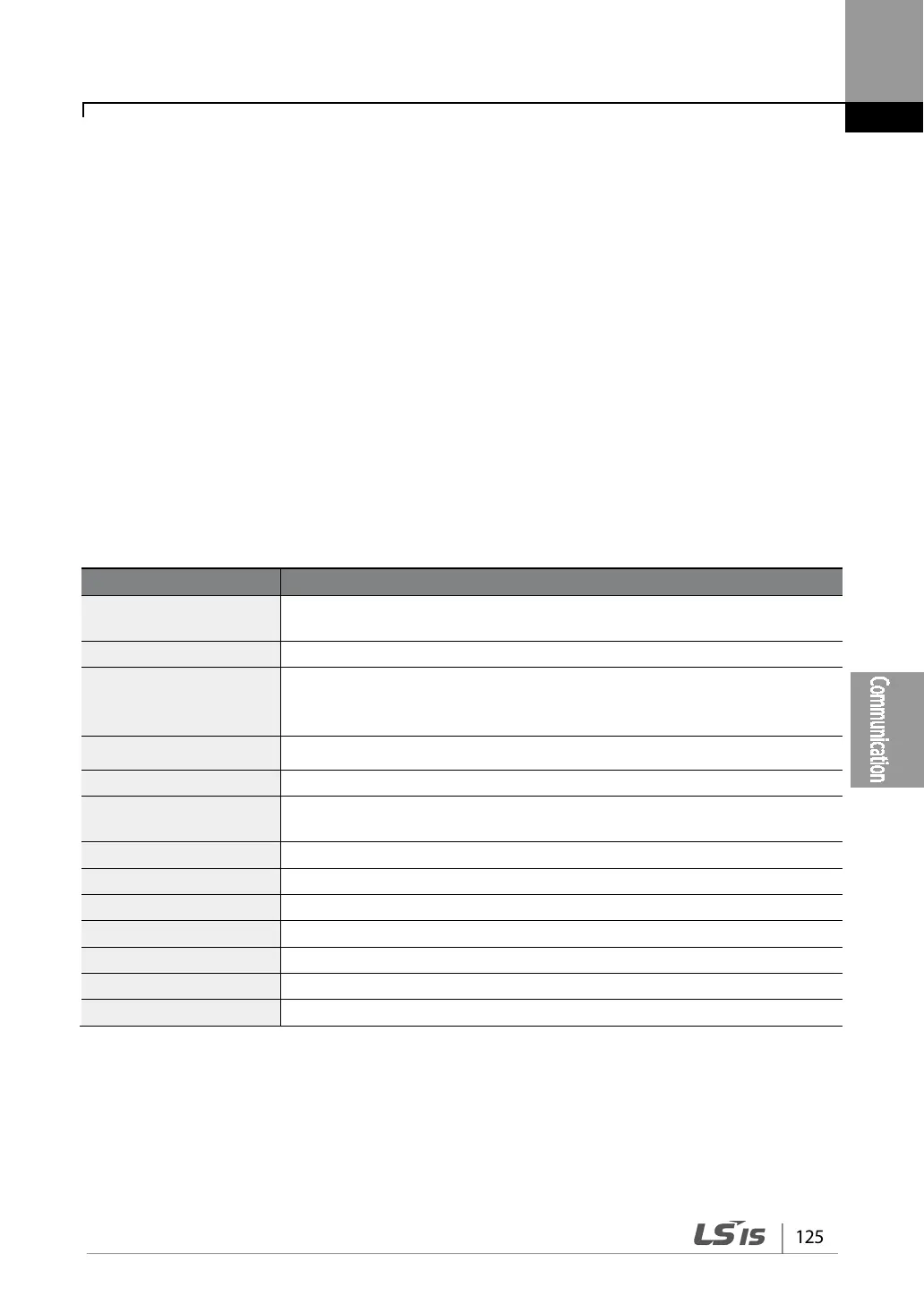
Communication method/
Transmission type
RS-485/Bus type, Multi-drop Link System
Inverter type name S100
inverters/ Transmission
Maximum of 16 inverters / Maximum1,200 m (recommended distance:
within 700 m)
Recommended cable size
0.75 mm², (18AWG), Shielded Type Twisted-Pair (STP) Wire
Dedicated terminals (S+/S-/SG) on the control terminal block
Power supply
Supplied by the inverter - insulated power source from the inverter’s
internal circuit
1,200/2,400/9,600/19,200/38,400/57,600/115,200 bps
Asynchronous communications system
Communication system Half duplex system
Modbus-RTU: Binary / LS Bus: ASCII
Parity check None/Even/Odd