9.7.4 Display Functions
DB Resistors connect with B1, B2 of DB Unit. DBU has 3 LEDs. Red LED which is located in middle
displays supplying main power, one Green LED which is right side displays under breaking and
another green LED which is left side displays Over Heat Trip(OHT).
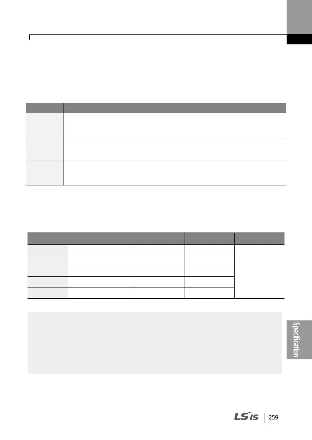
9.7.5 DB Resistors
Product(kW) DB Unit
Resistor(
Ω
)
Capacity(W) Reference
30kW
SV370DBU-4U
16.9
6,400
100% braking
torque,
10%ED
37kW
SV370DBU-4U
16.9
6,400
45kW
SV550DBU-4U
11.4
9,600
55kW
SV550DBU-4U
11.4
9,600
75kW
SV750DBU-4U
8.4
12,800
• The resistance/rated capacity/breaking torque/%ED of DB Resistor are valid only for the
DB unit of type A and the values of DB Resistor for type B and C refer to the manual of
DB Unit..
• Rating Watt of DBU has to be doubled when %ED is doubled.
Displays Function description
POWER
(Red LED)
POWER LED is turned On when main power is supplied.Generally, POWER LED is turn
On while main power supplied because DBU is connected with inverter.
RUN
(Green LED)
RUN LED is turned off while DBU is ON by regenerative energy of Motor.
OHT
(Green LED)
Under Breaking, if the temperature is exceeded over setting value due to over heat of
Heatsink, Cut the TURN ON signal of DBU and LED is turn on by working overheat
protection function.