RS-485 Communication Features
5.2.2 Setting Communication Parameters
Before proceeding with setting communication configurations, make sure that the
communication lines are connected properly. Turn on the inverter and set the communication
parameters.
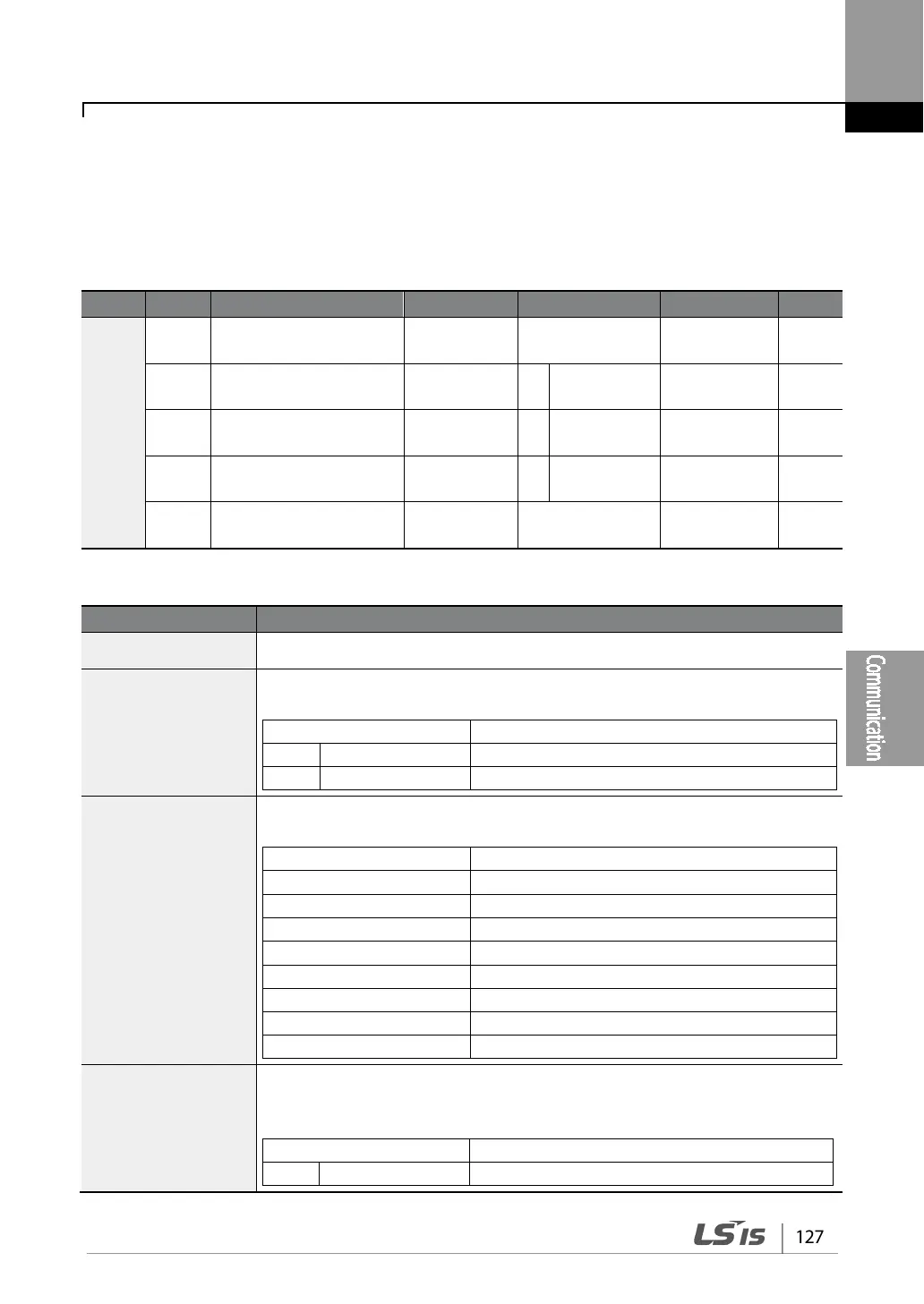
COM
01
Built-in communication
inverter ID
Int485 St ID 1 1-250 -
02
Built-in communication
protocol
Int485 Proto 0 ModBus RTU 0, 2 -
03
Built-in communication
speed
Int485 BaudR 3 9600 bps 0-7 -
04
Built-in communication
frame setting
Int485 Mode 0 D8/PN/S1 0-3 -
05
Transmission delay after
reception
Resp Delay 5 0-1000 ms
Communication Parameters Setting Details
COM-01 Int485 St ID Set the inverter station ID between 1 and 250.
COM-02 Int485 Proto
Select one of the two built-in protocols: Modbus-RTU or LS INV 485.
Modbus-RTU compatible protocol
Dedicated protocol for the LS inverter
COM-03 Int485 BaudR
Set a communication setting speed up to 115,200 bps.
COM-04 Int485 Mode
Set a communication configuration. Set the data length, parity check method,
and the number of stop bits.
8-bit data / no parity check / 1 stop bit