6 Table of Functions
This chapter lists all the function settings for S100 series inverter. Set the parameters required
according to the following references. If a set value input is out of range, the following messages
will be displayed on the keyboard. In these cases, the inverter will not operate with the [ENT] key.
• Set value not allocated: rd
• Set value repetition (multi-function input, PID reference, PID feedback related): OL
• Set value not allowed (select value, V2, I2): no
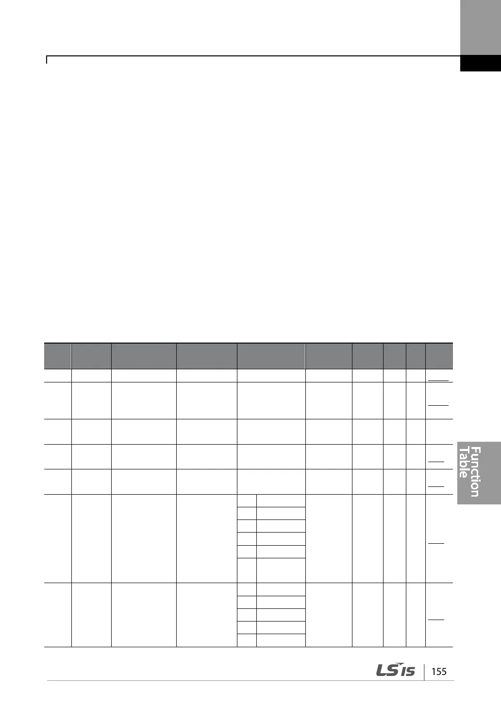
6.1 Drive group (PAR→DRV)
In the following table, data shaded in grey will be displayed when the related code has been
selected.
SL: Sensorless vector control (DRV-09) ,I – IM Sensorless, P – PM Sensorless
*O/X: Write-enabled during operation
Code
Name LCD Display Setting Range
Property*
V/F SL Ref.
01 0h1101
Target
frequency
Cmd
Frequency
- Maximum
0.00 O O I/P p.66
02 0h1102
Cmd Torque -180~180[%] 0.0 O X I -
03 0h1103
time
Acc Time 0.0-600.0(s) 20.0 O O I/P p.89
04 0h1104
Dec Time 0.0-600.0(s) 30.0 O O I/P p.89
06 0h1106
Command
source
Cmd Source
1:
Fx/Rx-1
X O I/P p.81
07 0h1107
Frequency
reference
source
Freq Ref Src
0:
Keypad-1
X O I/P p.66