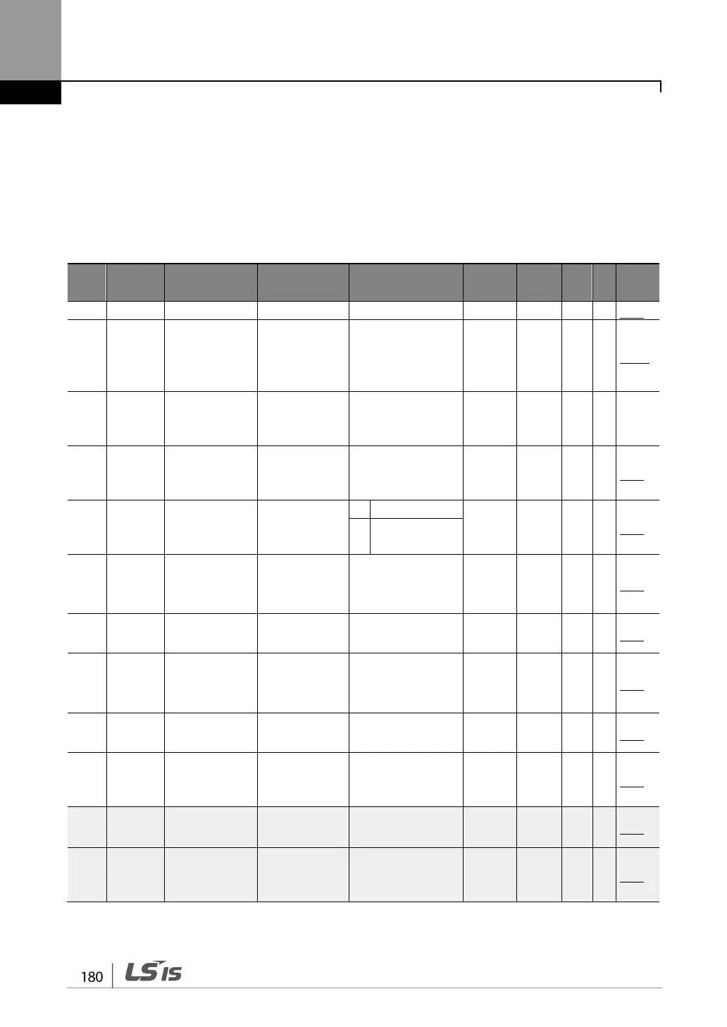
6.5 Input Terminal Block Function group (PAR→IN)
In the following table, the data shaded in grey will be displayed when a related code has been
selected.
SL: Sensorless vector control (DRV-09) , I – IM Sensorless, P – PM Sensorless
*O/X: Write-enabled during operation
Code
Name LCD Display Setting Range
Property*
V/F SL Ref.
01 0h1501
Frequency for
maximum
analog input
Freq at 100%
Start frequency-
Maximum
frequency(Hz)
um
freque
O O I/P p.67
02 0h1502
maximum
Torque
at100%
0.0-200.0(%) 100.0 O X X -
05 0h1505
voltage
V1 Monitor(V) -12.00-12.00(V) 0.00 O O I/P p.67
06 0h1506
polarity
V1 Polarity
Unipol
X O I/P p.67
1 Bipolar
07 0h1507
of V1 input
filter
V1 Filter 0-10000(ms) 10 O O I/P
p.67
08 0h1508
input voltage
V1 Volt x1 0.00-10.00(V) 0.00 O O I/P p.67
09 0h1509
Minimum
voltage (%)
V1 Perc y1 0.00-100.00(%) 0.00 O O I/P p.67
10 0h150A
input voltage
V1 Volt x2 0.00-12.00(V) 10.00 O O I/P p.67
11 0h150B
Maximum
V1 Perc y2 0.00-100.00(%) 100.00 O O I/P p.67
12
38
0h150C
V1 Minimum
input voltage
V1 –Volt x1’
-10.00- 0.00(V) 0.00 O O I/P p.72
13
38
0h150D
Minimum
V1 –Perc y1’
-100.00-0.00(%) 0.00 O O I/P p.72
38
Displayed when IN-06 is set to 1 (Bipolar)