4.19 2
nd
Operation Mode Setting
Apply two types of operation modes and switch between them as required. For both the first and
second command source, set the frequency after shifting operation commands to the multi-
function input terminal. Mode swiching can be used to stop remote control during an operation
using the communication option and to switch operation mode to operate via the local panel, or
to operate the inverter from another remote control location.
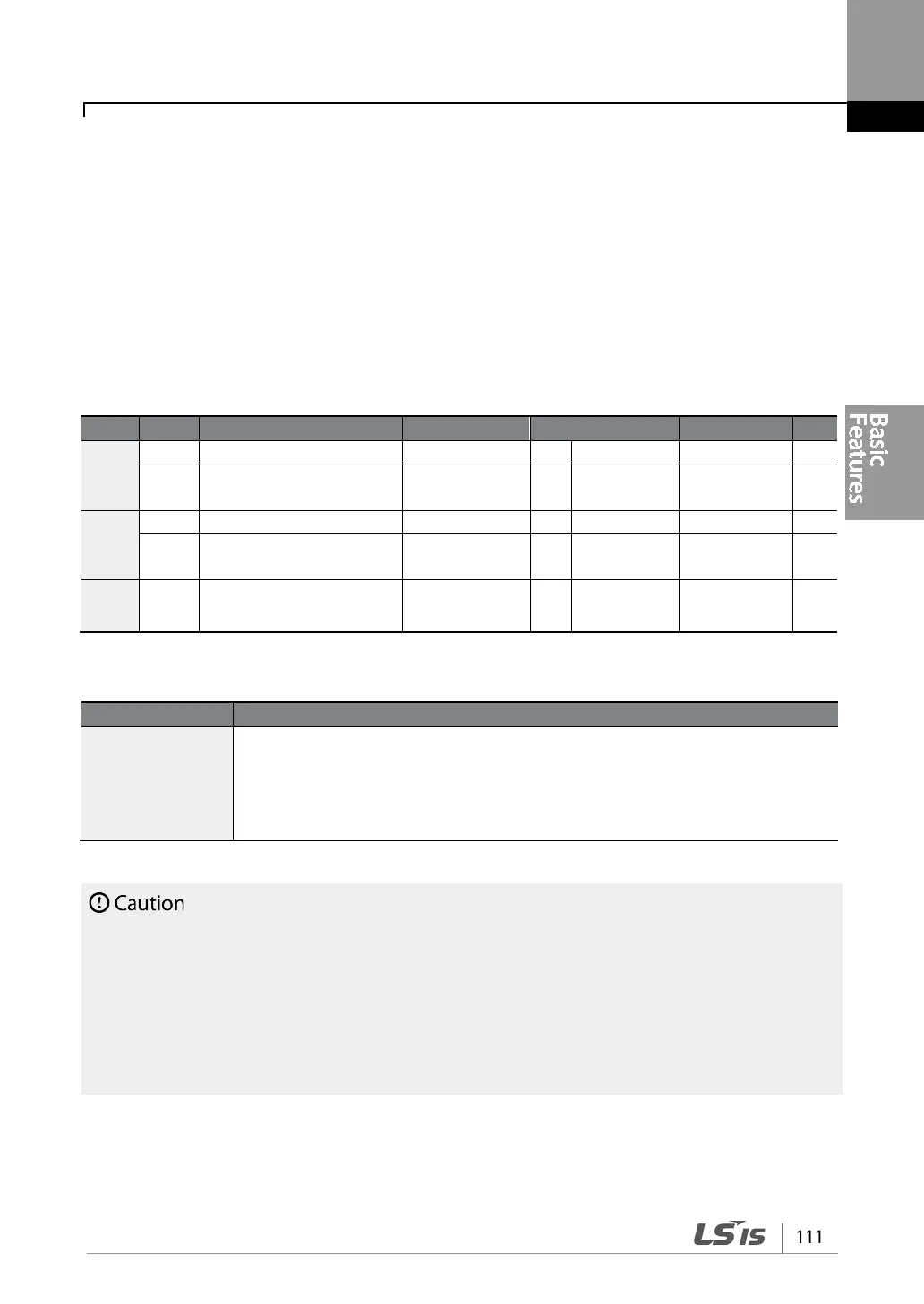
Select one of the multi-function terminals from codes IN- 65–71 and set the parameter value to 15
(2nd Source).
DRV
07
Frequency reference
source
Freq Ref Src 2 V1 0–12 -
BAS
05
2
nd
Frequency reference
source
Freq 2nd Src 0 KeyPad-1 0–12 -
IN
65–71
Px terminal configuration
(Px: P1–P7)
15 2nd Source 0–54 -
2nd Operation Mode Setting Details
BAS-04 Cmd 2nd
Src
BAS-05 Freq 2nd
Src
If signals are provided to the multi-function terminal set as the 2
nd
command
source (2nd Source), the operation can be performed using the set values from
BAS-04-05 instead of the set values from the 06 and 07 codes in the DRV group.
The 2nd command source settings cannot be changed while operating with the
st
command source (Main Source).
• When setting the multi-function terminal to the 2
nd
command source (2nd Source) and input (On)
the signal, operation state is changed because the frequency setting and the Operation command
will be changed to the 2
nd
command. Before shifting input to the multi-function terminal, ensure
that the 2
nd
command is correctly set. Note that if the deceleration time is too short or inertia of the
load is too high, an overvoltage fault trip may occur.
• Depending on the parameter settings, the inverter may stop operating when you switch the