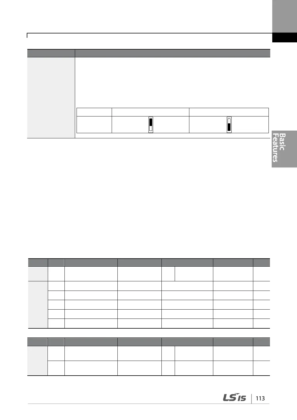
IN-90 DI Status
Display the configuration of each contact. When a segment is configured as A
terminal using DRV-87, the On condition is indicated by the top segment turning
on. The Off condition is indicated when the bottom segment is turned on. When
contacts are configured as B terminals, the segment lights behave conversely.
Terminals are numbered P1–P7, from right to left.
4.21 P2P Setting
The P2P function is used to share input and output devices between multiple inverters. To enable
P2P setting, RS-485 communication must be turned on .
Inverters connected through P2P communication are designated as either a master or slaves . The
Master inverter controls the input and output of slave inverters. Slave inverters provide input and
output actions. When using the multi-function output, a slave inverter can select to use either the
master inverter’s output or its own output. When using P2P communication, first designate the
slave inverter and then the master inverter. If the master inverter is designated first, connected
inverters may interpret the condition as a loss of communication.
Master Parameter
COM 95
P2P Communication
selection
Int 485 Func 1 P2P Master
0–3
-
USS
80 Analog input1 P2P In V1 0
0–12,000
%
81 Analog input2 P2P In I2 0
-12,000–12,000
%
82 Digital input P2P In DI 0
0–0x7F
bit
85 Analog output P2P Out AO1 0
0–10,000
%
88 Digital output P2P Out DO 0
0–0x03
bit
Slave Parameter
COM
95
P2P Communication
selection
Int 485 Func 2 P2P Slave
0–3
-
96
P2P OUT Sel 0 No
0–2
bit