Chapter 6 Basic Functions
6-4
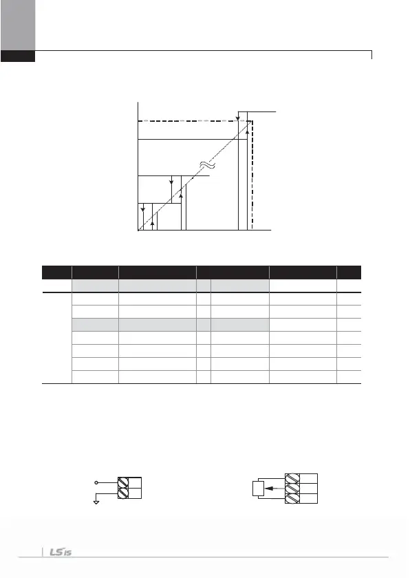
(3) If -10~+10V is input,
Group Code No. Function Display Setting Displayed Setting Range Unit
DRV 07 Freq Ref Src 2 V1 - -
IN
01 Freq at 100% - 60.00 0.00~Max. Freq. Hz
05 V1 Monitor - 0.00 0~10V V
06 V1 Polarity 1 Bipolar Unipolar/ Bipolar -
12 V1 -volt x1’ - 0.00 0~10V V
13 V1 -Perc y1’ - 0.00 0~100% %
14 V1 -Volt x2’ - -10.00 0~10V V
15 V1 -Perc y2’ - -100.00 0~100% %
Set IN-06 at Bipolar. Codes between 12 and 15 are displayed only when they are
Bipolar and you can set the voltage between 0 and 10V which is input into the V1
terminal.
As follows, input into the V1 terminal in volume resistance by using the voltage output
of the external controller or the VR output terminal of the inv erter control terminal block.
When -10~10V is used from the external circuit When connecting inner power source
V1
VR+
VR-
Analog
Input
Output
Frequency
Hz
[]
[V]
60.00
59.94
0.12
0.06
10
9. 9 75
9.925
0. 2
0.1750.0 7 5
0.025 0.1
V
1
G
-10 ~ +10 V
CM

 Loading...


