Chapter 6 Basic Functions
6-5
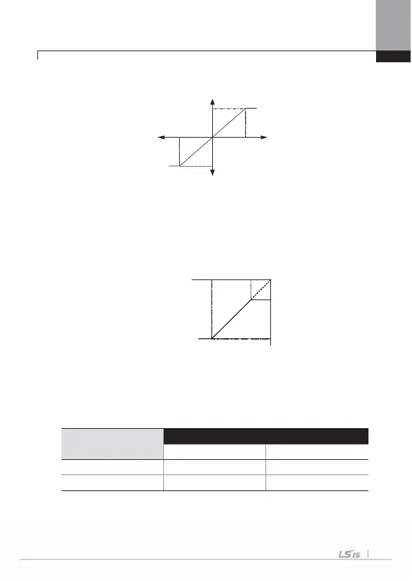
The output frequency of bipolar voltage input (-10~+10V) is as follows.
IN-12 V1 –volt x1’~ IN-15 V1 –Perc y2’: You can set the slope and offset value of the
output frequency of (-) input voltage as follows.
E.g.) If the minimum (-) input voltage if V1 is -2V, the output ratio of -2V is 10% and
maximum voltage is -8V and then you set the output ratio at 80%, the output
frequency moves between 6Hz~48Hz.
For setting of 0~+10V, see IN-08 V1 Volt X1 ~ IN-11 V1 Perc y2.
The selection of keypad or terminal block directions and motor rotation by bipolar
voltage input is shown in the following table.
Operating Command
Voltage Input
0~10V -10~0V
FWD FWD REV
REV REV FWD
Forward Output
Frequency
Input
Voltage
0~10[V]
Reverse Output
Frequency
-10 ~0[V]
V1 Input
IN - 14
IN - 12
IN - 13
Set
Frequency
IN - 15
48 Hz
6Hz
-2V-8V

 Loading...


