Chapter 8 Table of Functions
G
8-13
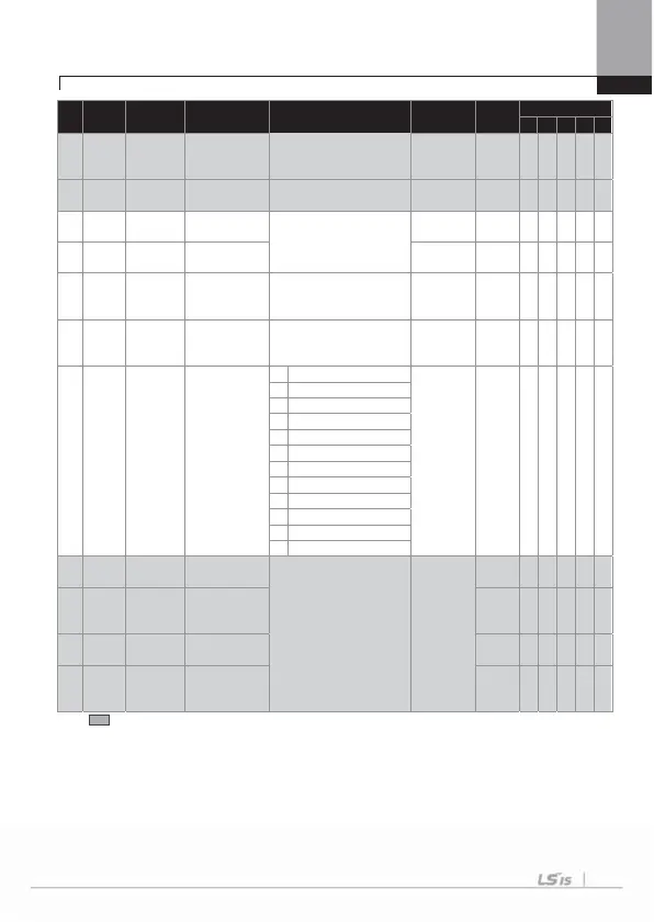
No.
Comm.
No.
Function
Display
Name Setting Range Initial Value
Shift in
Operation
Control Mod
V/F
SL
VC
SLT
VC
46
0h142E PG I Gain
PG operation
integral calculus
gain
50
O
O
X X X X
47
0h142F
PG Slip
Max%
PG operation
maximum sleep
0 ~ 200 100
X
ڪ
X X X X
48
-
CR P
Gain
Current control
period P gain
0 ~ 10000
1200
O X
ڪڪڪڪ
49
- ACR I Gain
Current control
period I gain
120
O X
ڪڪڪڪ
51
0h1433
ASR Ref
LPF
speed control
period
reference filter
0 ~ 20000 [ms] 0
X X
OO
XX
52
0h1434
Tor q u e Ou t
LPF
Torque control
period Output
filte
0 ~ 2000 [ms] 0
X X X X
OO
53
0h1435
Tor q u e L m t
Src
Torque limit
Setting method
0 Keypad-1
0 :Keypad-1
X
X X X
O
O
1 Keypad-2
2V1
3I1
4V2
5I2
6Int 48
7 Encode
8 FiedBu
9PL
10 Synchr
11 Binary Type
54
Note18)
0h1436
FWD +Trq
Lm
forward offsetting
Tor q u e li m i
0 ~ 200 [%] 180.0
O X X X
O O
55
0h1437
FWD –Trq
Lmt
forward
regenerative
torque limi
O X X X
O O
56
0h1438
REV +Trq
Lm
reverse offsetting
torque limi
O X X X
O O
57
0h1439
REV –Trq
Lmt
rever
e
regenerative
torque limit
O X X X
O O
* The grey code refers to hidden code, emerging only in case of setting of the code.
Note 16)
CON-23~28, 31~32 are displayed only when DRV-09 (Control Mode) is “Sensorless2” and
CON-20 (SL2 G View Sel) is set as “YES”.
Note 17)
CON-45~47 are displayed when Encoder Board is inserted and Control mode is V/F PG.
Note 18)
CON-54~57 are displayed only when DRV-09(Control Mode) is set as “Sensorless-1, 2”
or “Vector”. The initial value of torque limit will be changed to 150% with the setting of
ADV-74.

 Loading...


