Chapter 8 Table of Functions
G
8-29
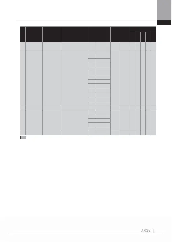
No. Comm. No. Function Display Name Setting Range
Initial
Value
Shift in
Operation
Control Mode
V/F
SL
VC
SLT
VCT
2
Beyond
Level
42
0h182A PID Unit Sel
PID control period unit
selection
0 %
0:% O
O
O
O
X X
1 Ba
2 mBa
3 Pa
4 KPa
5 H
6 rpm
7 V
8 I
9 kW
10 HP
11
12
එ
43
0h182B PID Unit Gain
PID unit gain
0
300 [%]
100.00
O
O
O
X X
44
0h182C
PID Unit
Scale
PID unit scale
0 X 100
2: x 1 O
O
O
O
X X
1 X 10
2 X 1
3 X 0.1
4 X 0.01
4
0h182D PID P2-Gain
PID
n
proportional gain
0
1000 [%]
100.0 X
O
O
O
X X
* The grey code refers to hidden code, emerging only in case of setting of the code.
Note 29)
APP 16~45 codes are displayed only when APP-01 (App Mode) is set as “Proc PID” or
APP-01(App Mode) is set as “MMC” and Requl Bypass(APO-34) is set as “No”.
G
G
G
G
G
G
G
G
G
G
G
G
G
G
G

 Loading...


