EasyManua.ls Logo

LSIS XEC-DP64H User Manual

LSIS XEC-DP64H
315 pages
To Next Page IconTo Next Page
To Previous Page IconTo Previous Page
Page #173 background imageLoading...
Page #173 background image
Chapter 5 Positioning Instructions
5 - 74
•When the instruction is executed, the sub-axis does not out real pulses (at this time, the in-
operation-state flag (X-axis: %KX6720, Y-axis: %KX6880) of the sub-axis is ON), and the STEP
of the sub-axis starts up when the main axis MST_AXIS is at the position set up in the
MST_ADDR.
•The position synchronization instruction can be executed only when the Origins for both of the
main axis and sub-axis have been determined. if the Origin of the main axis or sub-axis has not
been determined at the start of the APM_SSP instruction, error code 346 or 344, respectively, will
be outputted to STAT.
•When using this instruction, set up the main axis and sub-axis with different axis. Otherwise, error
code 347 will be outputted to STAT.
•To cancel the execution of position synchronization instruction after it is given, execute the stop
instruction (APM_STP) to the sub-axis.
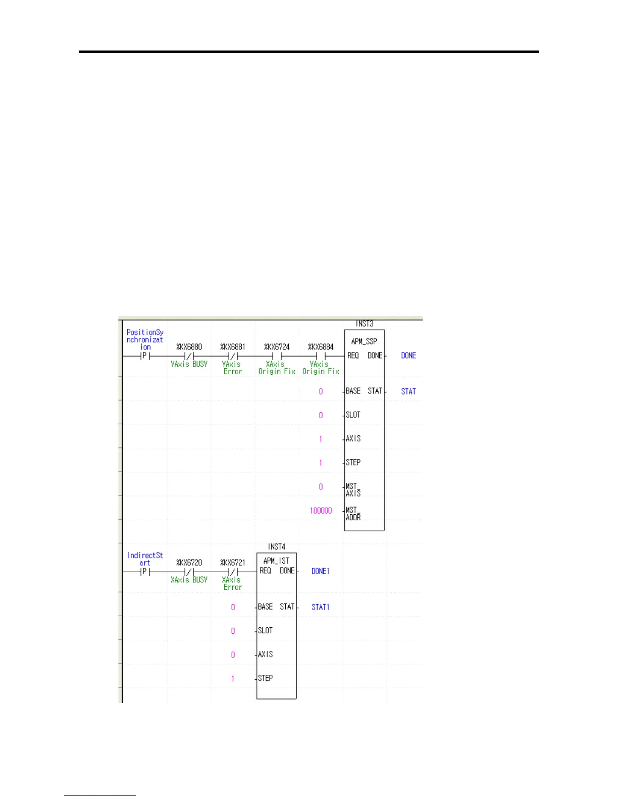
(2) Sample Instruction
•the sample program below shows the operation of the position synchronization start-up
instruction.
(a) Sample Program
•In the sample program below, where the Y-axis is the sub-axis and X-axis is the main axis, when
the main axis position is at 100,000, the operation data in the No. step of the sub-axis is started
up.

Table of Contents

Questions and Answers:

LSIS XEC-DP64H Specifications

General IconGeneral
BrandLSIS
ModelXEC-DP64H
CategoryController
LanguageEnglish

Summary

XGB Built-in Positioning

Safety Instruction

Crucial safety guidelines to be followed before operating the product.

Chapter 1 General

Provides general information about the positioning function, including purpose and features.

Chapter 2 General Specification

Provides general specifications for the XGB series, including environmental and immunity details.

Chapter 3 Before Positioning

Explains various positioning functions, parameters, and operation data.

Chapter 4 Positioning Check

Outlines the procedure for testing XGB positioning operation before use.

Chapter 5 Positioning Instructions

Provides detailed explanations for various positioning instructions like Origin Return, Direct Start, etc.

Chapter 6 Positioning Monitoring Package

Introduces the XGB positioning monitoring package for status monitoring and test operation.

Chapter 7 Program Examples of Positioning

Provides practical program examples for various positioning functions.

Chapter 8 Troubleshooting Procedure

Outlines basic steps for troubleshooting errors in XGB PLC and positioning functions.

Appendix 1 List of Error Codes

Details specific error codes related to the XGB positioning function.

Appendix 2 Positioning Instruction and K area List

Provides a list of dedicated K areas for positioning parameters and instructions.

Appendix 3 Motor Wiring Example

Illustrates wiring examples for connecting XGB PLC to servo motors.

Appendix 4 Dimension

Provides dimensional drawings for standard XGB main units (XBM-DN/DR series).

Related product manuals