EasyManua.ls Logo

LSIS XEC-DP64H User Manual

LSIS XEC-DP64H
315 pages
To Next Page IconTo Next Page
To Previous Page IconTo Previous Page
Page #180 background imageLoading...
Page #180 background image
Chapter 5 Positioning Instructions
5 - 81
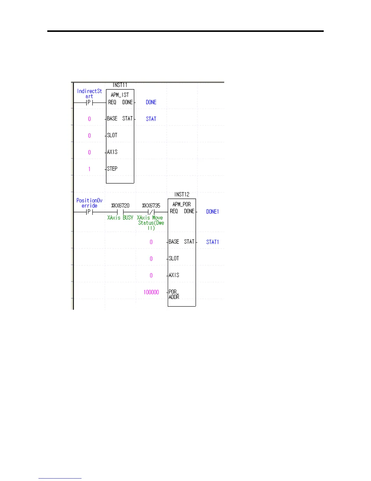
(2) Sample Instruction
•The sample program below show exemplary operation of position override.
(c) Sample Program
(d) Program Operation
•At the rising edge of the ‘indirect start-up’ signal which is the reference signal for indirect start-up,
positioning X-axis is started up indirectly by operation step No. 1.
•If the rising edge of the ‘position override reference’ signal used as the reference signal for the
position override instruction occurs before the present position reaches 100,000[Pulse] during
operation, the operation continues by changing the target position of the step presently in
operation to 100,000. Take care that the target position value of the No.1 step set up with the
positioning parameter itself is not changed.
•If position override instruction is executed after the present position has passed 100,000[Pulse],
deceleration stop occurs.
•If position override instruction is executed while the operation state is in dwelling, error code 362 is
outputted to STAT. To prevent this, the start-up contact should be connected with the X-axis dwell
status flag as normally closed (B contact) in the program.

Table of Contents

Questions and Answers:

LSIS XEC-DP64H Specifications

General IconGeneral
BrandLSIS
ModelXEC-DP64H
CategoryController
LanguageEnglish

Summary

XGB Built-in Positioning

Safety Instruction

Crucial safety guidelines to be followed before operating the product.

Chapter 1 General

Provides general information about the positioning function, including purpose and features.

Chapter 2 General Specification

Provides general specifications for the XGB series, including environmental and immunity details.

Chapter 3 Before Positioning

Explains various positioning functions, parameters, and operation data.

Chapter 4 Positioning Check

Outlines the procedure for testing XGB positioning operation before use.

Chapter 5 Positioning Instructions

Provides detailed explanations for various positioning instructions like Origin Return, Direct Start, etc.

Chapter 6 Positioning Monitoring Package

Introduces the XGB positioning monitoring package for status monitoring and test operation.

Chapter 7 Program Examples of Positioning

Provides practical program examples for various positioning functions.

Chapter 8 Troubleshooting Procedure

Outlines basic steps for troubleshooting errors in XGB PLC and positioning functions.

Appendix 1 List of Error Codes

Details specific error codes related to the XGB positioning function.

Appendix 2 Positioning Instruction and K area List

Provides a list of dedicated K areas for positioning parameters and instructions.

Appendix 3 Motor Wiring Example

Illustrates wiring examples for connecting XGB PLC to servo motors.

Appendix 4 Dimension

Provides dimensional drawings for standard XGB main units (XBM-DN/DR series).

Related product manuals