Chapter 3 Before positioning
3- 10
3) Setting of operation pattern
- In case of main axis, operation pattern should be specified as ‘END’ or ‘KEEP’. In case it is
specified as ‘CONT’, it operates as ‘KEEP’.
- In case of subsidiary, pattern doesn’t affect the operation, it operates according to main axis
pattern.
(b) Example
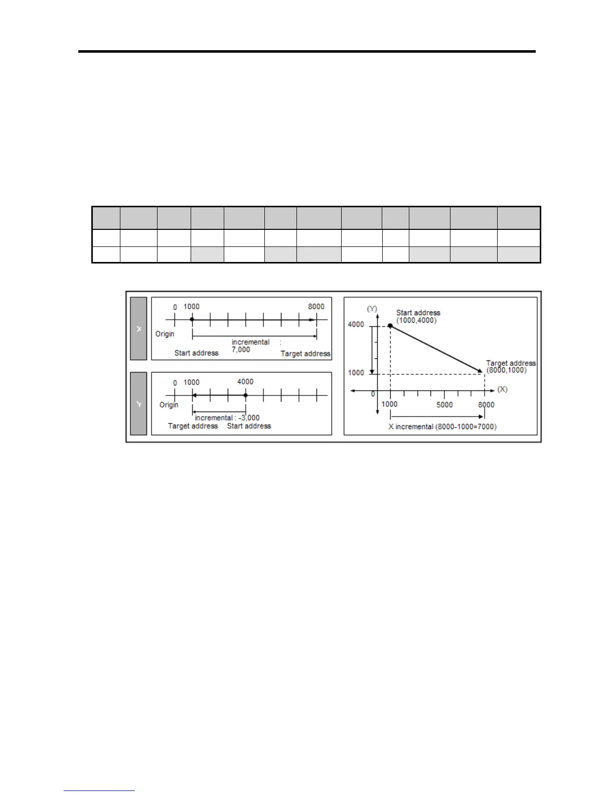
• It assumes that operation data is specified as shown table 3-6 and current position are
X=1000 , Y=4000.
Step
no.
Coord. Pattern Control Method
Rep
step
Address
[Pulse]
M
Code
A/D
No.
Speed
[pls/s]
Dwell [㎳] Step no.
X 1 ABS END POS SIN 0 8000 0 0 500 100
Y 1 ABS KEEP POS REP 3 1000 0 0 2000 20
<Table 3-6 operation data example of linear interpolation control by absolute coordinates>
< Figure 3-6 linear interpolation operation by absolute coordinates >
• If linear interpolation starts, main axis is determined automatically based on moving amount of X
and Y axis. In table 3-6, since moving amount of X axis is larger than Y axis X, X axis becomes
main axis.
• So operation pattern, speed, A/D number, dwell time of Y axis is ignored and it is specified
automatically according to operation data of X axis.
• Figure 3-7 indicates operation of linear interpolation control.