EasyManua.ls Logo

LSIS XEC-DP64H User Manual

LSIS XEC-DP64H
315 pages
To Next Page IconTo Next Page
To Previous Page IconTo Previous Page
Page #50 background imageLoading...
Page #50 background image
Chapter 3 Before positioning
3- 13
3.1.8 Sync control
•In sync control, position or speed of subsidiary axis is synchronized with that of main axis. There are
two types in sync control, speed sync control and position sync control.
(1) Position sync control
• Position sync control means starting the operation step of subsidiary at the time when position of
main axis is same with position set in SSP instruction (Sync control)
• Position sync control can be executed when origin of both axes is determined. When executing
the SSP instruction, if origin of main axis is not determined, error code 346 occurs and for
subsidiary axis, error code 344.
• When using SST instruction, specify the main axis to be different with subsidiary axis. If not, error
code 347 will occur.
• If synch control is executed, though pulse is not yielded until main axis goes to designated axis,
flag indicating whether subsidiary axis moves or not, turns on (X axis: K4200, %KX6720, Y axis:
K4300, %KX6880).
• After executing position sync control, if the user wants to cancel the execution of position sync
control, execute the STP instruction (stop command).
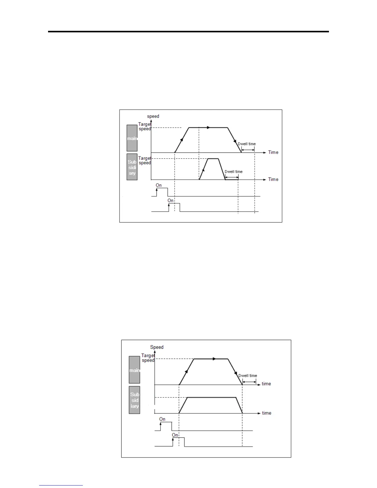
(2) Speed sync control
If main axis starts as figure below, subsidiary axis moves with speed of sync speed rate set in
the SSS instruction (speed sync command).
Sync position
Start Position
sync
St
ar
t
ma
i
n
ax
i
s
Sync
speed
Start sync
control
Start main
axis

Table of Contents

Questions and Answers:

LSIS XEC-DP64H Specifications

General IconGeneral
BrandLSIS
ModelXEC-DP64H
CategoryController
LanguageEnglish

Summary

XGB Built-in Positioning

Safety Instruction

Crucial safety guidelines to be followed before operating the product.

Chapter 1 General

Provides general information about the positioning function, including purpose and features.

Chapter 2 General Specification

Provides general specifications for the XGB series, including environmental and immunity details.

Chapter 3 Before Positioning

Explains various positioning functions, parameters, and operation data.

Chapter 4 Positioning Check

Outlines the procedure for testing XGB positioning operation before use.

Chapter 5 Positioning Instructions

Provides detailed explanations for various positioning instructions like Origin Return, Direct Start, etc.

Chapter 6 Positioning Monitoring Package

Introduces the XGB positioning monitoring package for status monitoring and test operation.

Chapter 7 Program Examples of Positioning

Provides practical program examples for various positioning functions.

Chapter 8 Troubleshooting Procedure

Outlines basic steps for troubleshooting errors in XGB PLC and positioning functions.

Appendix 1 List of Error Codes

Details specific error codes related to the XGB positioning function.

Appendix 2 Positioning Instruction and K area List

Provides a list of dedicated K areas for positioning parameters and instructions.

Appendix 3 Motor Wiring Example

Illustrates wiring examples for connecting XGB PLC to servo motors.

Appendix 4 Dimension

Provides dimensional drawings for standard XGB main units (XBM-DN/DR series).

Related product manuals