Chapter 3 Before positioning
3- 39
(1) Home Return method
• There are three home return methods as follows.
a) DOG/Origin(Off) :
-If origin signal is inputted, it detects the origin signal after DOG changes On -> Off.
b) DOG/Origin(On) : When DOG is on, it detects the origin after deceleration
-If DOG signal is on and origin signal is inputted after deceleration, it detects the origin.
c) DOG :
-It detects the origin by using DOG signal.
• For more detail of home return method, refer to 3.1.9.
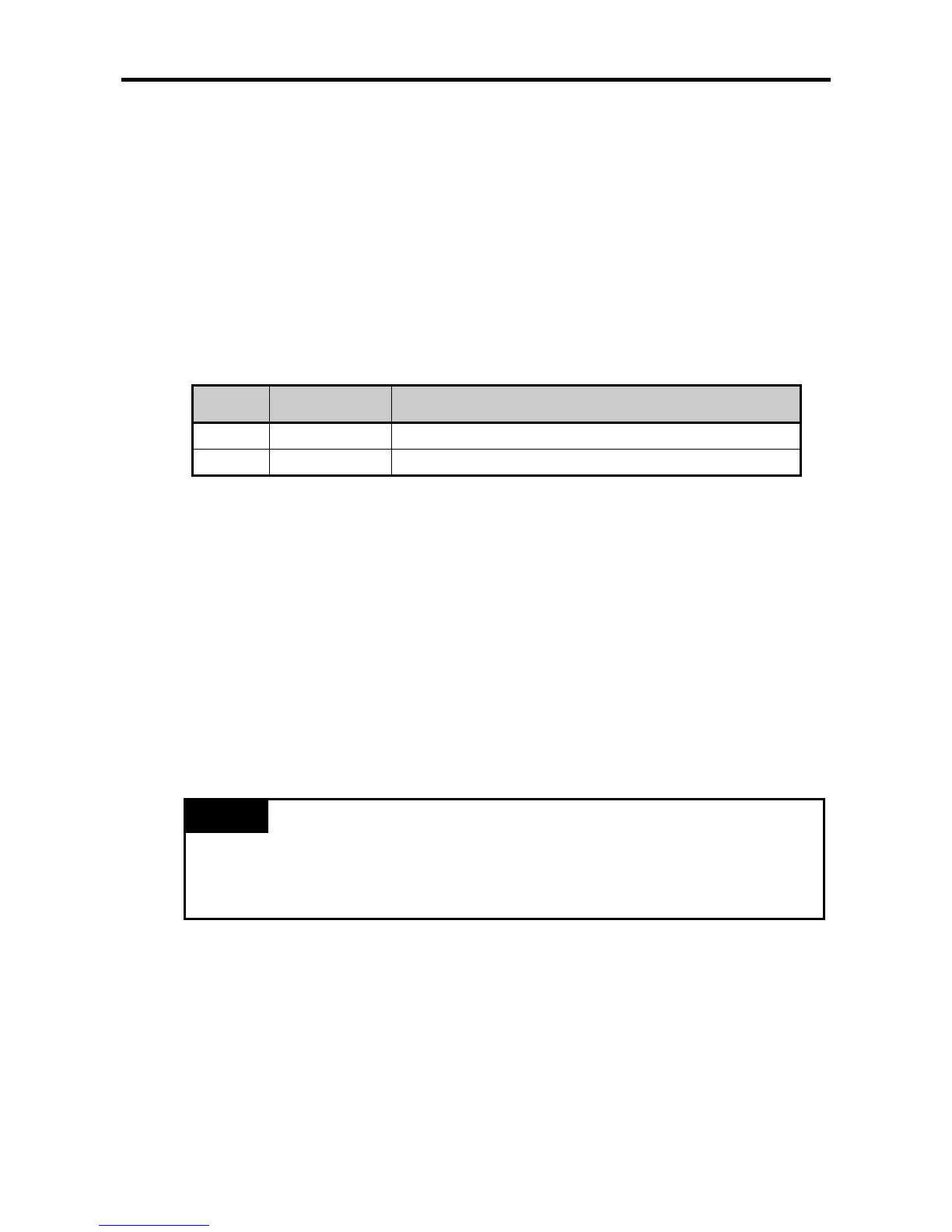
(2) Home Return direction
• Home Return direction is divided into CW(forward) and CCW(backward) depending on pulse output
direction.
Setting
value
Home Return
direction
Pulse output operation of XGB positioning module
0 Forward Executing forward home return.
1 Backward Executing backward home return.
(3) Origin address
• It is used to change the current address to a value set in home return address when home return is
completed by home return instruction.
• setting range: -2,147,483,648 2,147,483,647∼ (unit: Pulse)
(4) Home Return high speed
• As a speed when it returns home by home return instruction, it is divided into high speed and low
speed.
• It refers to a speed operating in regular speed section via accelerating section by home return
instruction.
•
The range of home return high speed is between 1 100,000(unit: pps)∼
(5) Home Return low speed
• It refers to a speed operating in regular speed section via decelerating section from home return
high speed by home return instruction.
• The range of home return low speed is between 1 ∼ 100,000(unit: pps)
Remark
• When setting home return speed, it should be “speed limit ≥ home return high speed ≥ home
return low speed”.
• It is recommended to set home return low speed as low as possible when setting home return
speed. Origin signal detection may be inaccurate if low speed is set too fast.
(6) Home Return ACC/DEC time
• When it returns home by home return instruction, it returns home at the speed of home return high
speed and home return low speed by ACC/DEC time.
• The range of home return ACC/DEC time is between 0 ∼ 10,000(unit: 1 ㎳).
(7) Dwell
time
• It sets Dwell time applied to Home Return
• Dwell time is necessary to maintain precise stop of servo motor when positioning by using a servo
motor.
• The actual duration necessary to remove remaining pulse of bias counter after positioning ends is
called ‘dwell time’.