116
SC100/200 Series Users Manual EM-6337-B Rev.15
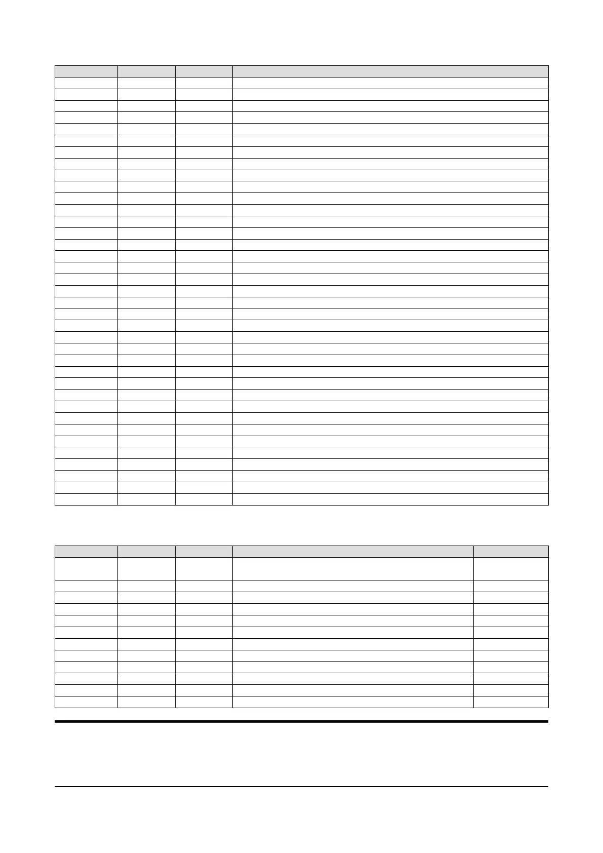
FIELD TERMINAL
REGISTER PARAMETER R/W DESCRIPTION
40901 PV1 R PV1 input (-15.00 to 115.00%, Data range -1500 to 11500)
40902 PV2 R PV2 input (-15.00 to 115.00%, Data range -1500 to 11500)
40903 AI1 R AI1 input (-15.00 to 115.00%, Data range -1500 to 11500)
40904 AI2 R AI2 input (-15.00 to 115.00%, Data range -1500 to 11500)
40905 AI3 R AI3 input (-15.00 to 115.00%, Data range -1500 to 11500)
40906 AI4 R AI4 input (-15.00 to 115.00%, Data range -1500 to 11500)
40907 MV1 R MV1 output (-15.00 to 115.00%, Data range -1500 to 11500)
40908 MV2 R MV2 output (-15.00 to 115.00%, Data range -1500 to 11500)
40909 AO1 R AO1 output (-15.00 to 115.00%, Data range -1500 to 11500)
40910 AO2 R AO2 output (-15.00 to 115.00%, Data range -1500 to 11500)
40911 PI1 R PI1 input (0 to 9999, Data range 0 to 9999)
40912 PI2 R PI2 input (0 to 9999, Data range 0 to 9999)
40913 PI3 R PI3 input (0 to 9999, Data range 0 to 9999)
40914 PI4 R PI4 input (0 to 9999, Data range 0 to 9999)
40915 PI5 R PI5 input (0 to 9999, Data range 0 to 9999)
40916 PI6 R PI6 input (0 to 9999, Data range 0 to 9999)
40917 FN1 R FN1 indication (-15.00 to 115.00%, Data range -1500 to 11500)
40918 FN2 R FN2 indication (-15.00 to 115.00%, Data range -1500 to 11500)
40919 FN3 R FN3 indication (-15.00 to 115.00%, Data range -1500 to 11500)
40920 FN4 R FN4 indication (-15.00 to 115.00%, Data range -1500 to 11500)
901 DI1 R DI1 input
902 DI2 R DI2 input
903 DI3 R DI3 input
904 DI4 R DI4 input
905 DI5 R DI5 input
906 DO1 R DO1 output
907 DO2 R DO2 output
908 DO3 R DO3 output
909 DO4 R DO4 output
910 DO5 R DO5 output
911 RUN R RUN contact (0: Error, 1: Normal)
912 AL1 R AL1 lamp
913 AL2 R AL2 lamp
914 AL3 R AL3 lamp
915 AL4 R AL4 lamp
916 DI6 R DI6 input
Read only for output data. Use Communication Terminal to write.
SYSTEM
REGISTER PARAMETER R/W DESCRIPTION EQUIVALENT TO
1001 MAINTE R Maintenance status (0 in the monitor mode at GR 02 and GR 03
ITEM 01, 1 in others)
----
1002 RUN R Control status (0: Run, 1: Stop) GR 00 ITEM 02
1003 EEPERR R EEPROM data base failed (0: Normal, 1: Error) GR 00 ITEM 21
1004 PVERR R PV abnormality (0: Normal, 1: Error) GR 00 ITEM 22
1005 MVAERR R MV feedback abnormality (0: Normal, 1: Error) GR 00 ITEM 23
1006 MODERR R Function block abnormality (0: Normal, 1: Error) GR 00 ITEM 24
1007 OVERLOAD R Control overload (0: Normal, 1: Overload) GR 00 ITEM 25
1008 BACKRUN R Backup module status (0: Normal, 1: Error) ----
41001 EEPGRP R EEPROM error group (with EEPRR = 1) ----
41002 MODGRP R Function block error group (with MODERR = 1) ----
41003 BACKSTATUS R Backup status (0: Normal, 1: Standby, 1: Running) ----
NOTE
When more than one error has occurred among EEPERR, PVERR, MVAERR, MODERR and OVERLOAD, the most criti-
cal error is set with “1.” Priority is given as: EEPERR > PVERR > MVAERR > MODERR > OVERLOAD.
For example, MODERR is set with “1” when both MODERR and OVERLOAD are in error. Then OVERLOAD turns to “1”
after MODERR error is cancelled.