215651 40 Revision B
&
$
%
&
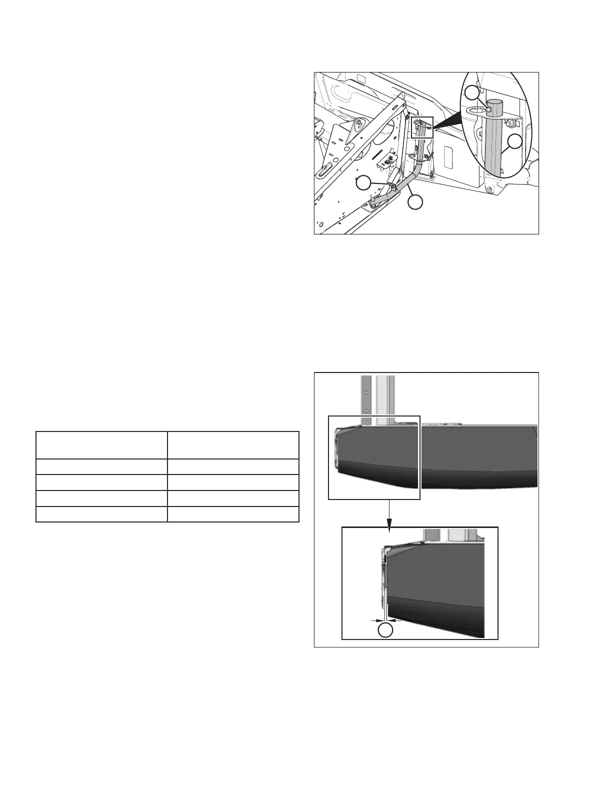
Figure 3.13: Left Endshield on D1X Series
Draper Header
1. Guide the endshield onto hinge arm (C) and slowly lower it.
NOTE:
Ensure hinge arm (C) is installed in the outboard hole on
the hinge bracket, as shown in the illustration at right.
2. Install self-tapping screw (B).
3. Disengage lock (A) to allow endshield movement.
4. Close the endshield. For instructions, refer to Closing
Endshields, page 38 .
NOTE:
Endshields may expand or contract when subjected to large
temperature changes. The top pin and lower latch bracket
positions can be adjusted to compensate for dimensional
changes. For instructions, refer to Checking and Adjusting
Endshields, page 40 .
Checking and Adjusting Endshields
The header’s endshields are made from molded plastic and are therefore subject to expansion or contraction caused by
variations in the ambient temperature. The position of the top pin and that of the lower latch can be adjusted to
compensate for dimensional changes in the endshield.
Checking the endshield
;
Figure 3.14: Gap between Endshield and
Header Frame
1. Measure gap (X) between the front end of the endshield
and the header frame. Compare the measurement to the
values provided in Table 3.1, page 40 .
Table 3.1 Endshield Gaps at Various Ambient Temperatures
Ambient Temperature °C (°F)
Expected Gap (X)
mm (in.)
7 (45)
13–18 (1/2–23/32)
18 (65)
10–15 (3/8–19/32)
29 (85)
7–12 (9/32–15/32)
41 (105)
4–9 (5/32 –11/32)
OPERATION