214366 98 Revision A
4.7 Cutting Height
Cutting height is determined by a combination of the angle of the cutterbar/header and the optional gauge roller or
skid shoe settings if installed. Cutting height should be adjusted for optimum cutting performance without excessive
mud build-up inside the header that can lead to poor crop flow and increased wear on cutting components. Choose
an angle that maximizes performance for your crop and field conditions. Refer to 4.6 Header Angle, page 97.
Optional adjustable gauge rollers or skid shoes are also available to provide different cutting heights. Refer to:
• 6.1 Options and Attachments: Kits, page 175
• 4.7.1 Adjusting Gauge Roller Height, page 98
• 4.7.2 Adjusting the Skid Shoe Height, page 99
Lowering the skid shoes/gauge rollers or decreasing header angle increases the cutting height. This may reduce
damage to cutting components in stony conditions. Also, a longer stubble length helps material dry faster.
Raising the skid shoes/gauge rollers and increasing header angle allows the crop to be cut lower.
To minimize damage to cutterbar components, scooping soil, or soil build-up at the cutterbar in damp conditions,
set header float as light as possible without excessive bouncing.
A light float setting may require reduced ground speeds to avoid excess bouncing and a ragged cut.
4.7.1 Adjusting Gauge Roller Height
Optional adjustable gauge rollers are available to provide different cutting heights.
DANGER
To avoid bodily injury or death from unexpected start-up or fall of raised machine, stop engine, remove
key, and engage header safety props before going under machine for any reason.
To adjust gauge roller height, follow these steps:
1. Raise the header fully.
2. Stop the engine and remove the key.
3. Engage header safety props. Refer to 3.3 Engaging and
Disengaging Header Safety Props, page 28.
1010654
A
B
C
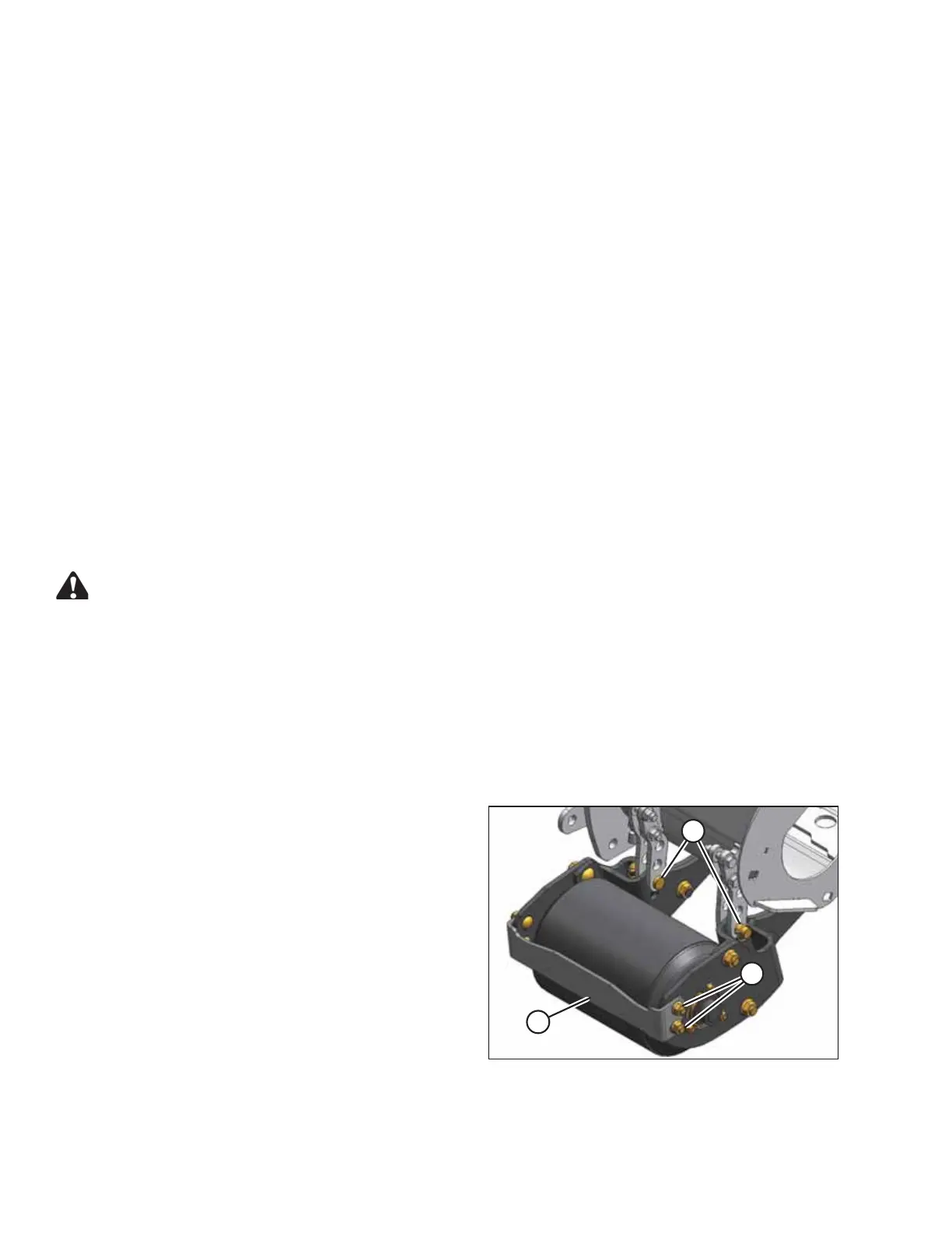
Figure 4.24: Gauge Roller
4. Remove lynch pin and remove adjuster pin (A) from one
side of the roller.
5. Hold roller and remove lynch pin and adjuster pin (A)
from other side. Position roller at desired position and
reinstall adjuster pins (A). Secure with lynch pins.
6. Repeat for roller at opposite end of header.
7. Adjust mud bar (B) by loosening nuts (C).
8. Retighten nuts (C) while maintaining a minimum
clearance between mud bar and roller.
OPERATING THE HEADER