214366 165 Revision A
Replacing the Header Drive Speed Sensor
1014202
A
A
B
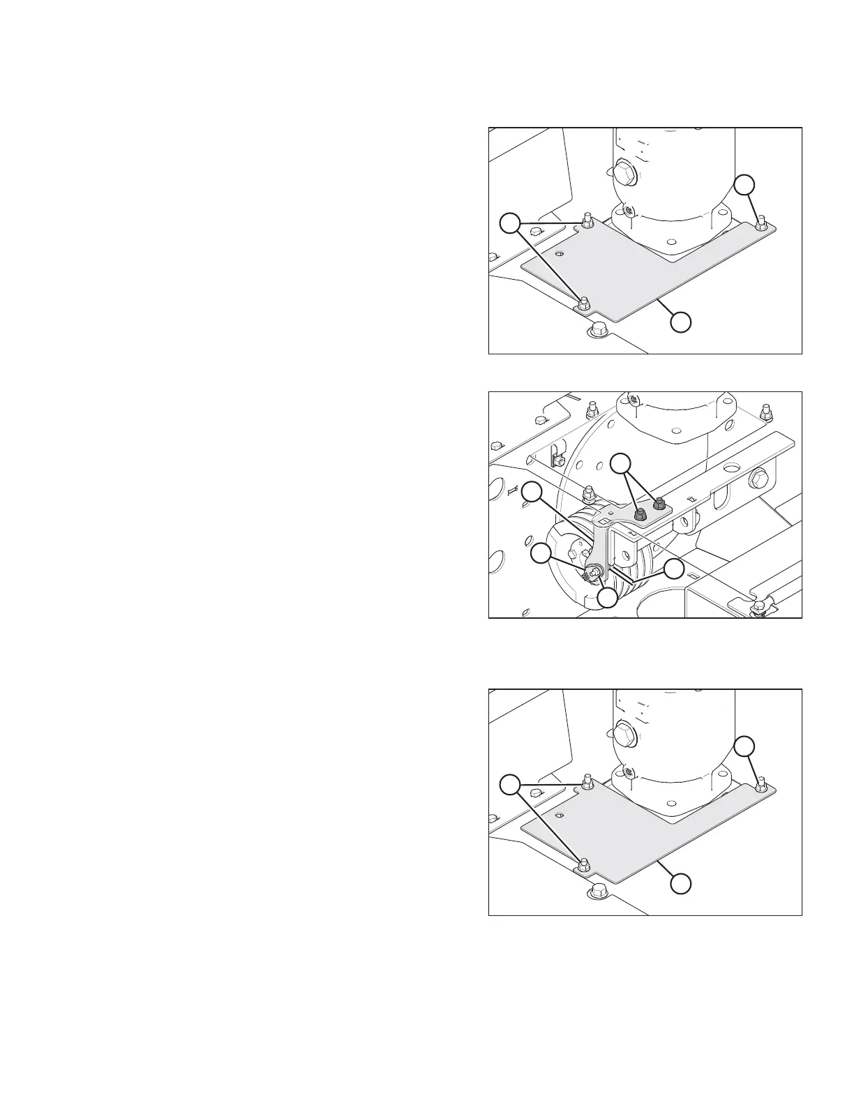
Figure 5.60: Header Drive Cover
1. Loosen bolts (A) and remove cover (B).
1014206
A
B
C
D
E
Figure 5.61: Header Drive Speed Sensor
2. Cut and remove cable tie securing harness to
bracket (C).
3. Unplug sensor wire from connector (A).
4. Remove nut and bolt (E) securing sensor (A) to
bracket (C) and remove sensor (A).
5. Install new sensor (A) onto bracket (C) with bolt and
nut (E). Ensure sensor is aligned with the pulley rim.
6. Check that gap (B) between sensor and pulley is
0.08 in. (2 mm). Adjust as required.
7. Connect sensor wire to connector (A).
8. Secure harness to bracket with plastic tie.
NOTE:
Top panel removed for clarity.
1014202
A
A
B
Figure 5.62: Header Drive Cover
9. Reinstall cover (B) and secure with bolts (A).
MAINTENANCE AND SERVICING