214366 81 Revision A
4 Operating the Header
Your header will provide the best performance when it is properly adjusted to suit the crop and conditions.
Correct operation reduces crop loss and increases productivity. As well, proper adjustments and timely
maintenance will increase the length of service you receive from the machine.
The variables listed below and detailed on the following pages will affect the performance of the header. You will
quickly become familiar with adjusting the machine to give you the desired results. Most of the adjustments have
been set at the factory, but if desired, the settings can be changed to suit crop conditions.
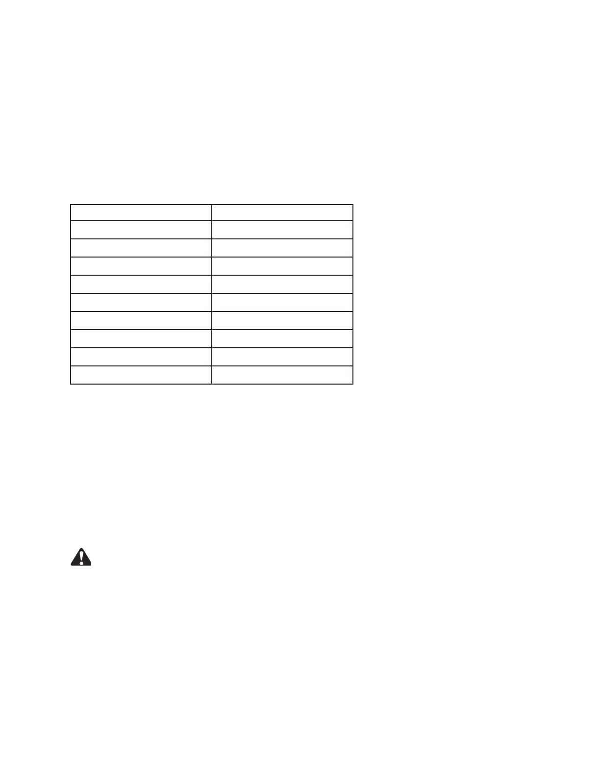
Table 4.1 Header Adjustment Procedures
Variable
Refer to
Header float
4.1 Header Float, page 81
Roll gap
4.2 Roll Gap, page 86
Roll tension 4.3 Roll Tension, page 89
Roll timing
4.4 Roll Timing, page 90
Forming shields
4.5 Forming Shields, page 93
Header angle 4.6 Header Angle, page 97
Cutting height 4.7 Cutting Height, page 98
Disc speed
4.8 Disc Speed, page 100
Ground speed 4.9 Ground Speed, page 101
4.1 Header Float
Header float springs are normally set so 426–471 N (95–105 lbf) is required to lift the header at either end.
In rough or stony conditions, it may be desirable to maintain a lighter setting to protect cutting components.
When float setting is light, it may be necessary to use a slower ground speed to avoid excessive bouncing resulting
in a ragged cut. Faster ground speeds may require additional ground pressure.
Up to three user-defined float positions can be stored in the windrower's control system. For information on setting
float, refer to the Float Options topic in the windrower operator's manual.
4.1.1 Checking Float – M200 and M205 Windrowers
DANGER
To avoid bodily injury or death from unexpected startup of the machine, always stop the engine and
remove the key from the ignition before leaving the operator’s seat for any reason.
Set the float fine adjustment to MID-RANGE with the windrower float adjustment system in the cab (refer to your
windrower operator’s manual).
1. Lower the header until lift cylinders are fully retracted.
2. Stop the engine and remove the key.
3. Grasp the front corner of the header and lift. The force required to lift the header should be 426–471 N (95–105
lbf) and should be approximately the same at both ends. If adjustment is required, refer to 4.1.2 Adjusting Float