214366 76 Revision A
1005199
A
B
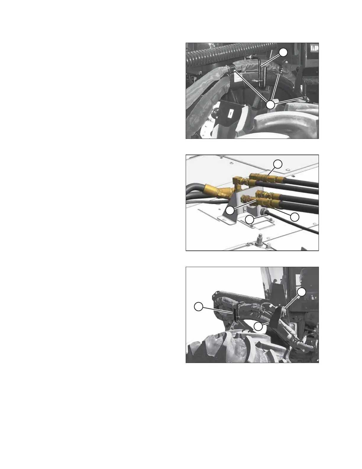
Figure 3.98: Hose Bundle
7. Raise and unlock lever (A) and undo the three cinch
straps (B).
8. Move hose bundle to store on header.
1006066
A
B
C
D
Figure 3.99: Hydraulic Connections
9. At the header, disconnect electrical connector (D) by
turning the collar counterclockwise and pulling
connector to disengage.
10. Disconnect the pressure (A), return (B), and case
drain (C) hoses.
1005217
A
B
C
Figure 3.100: Hose Bundle
11. Move the hose bundle from header to the left-side (cab-
forward) hose support (B).
12. Rotate lever (A) clockwise and push to engage bracket.
13. Route the electrical harness through hose support (B)
and attach cap to electrical connector (C).
OPERATION