IMPULSE
®
•G+ & VG+ Series 4 Technical Manual
November 2020
Page 190
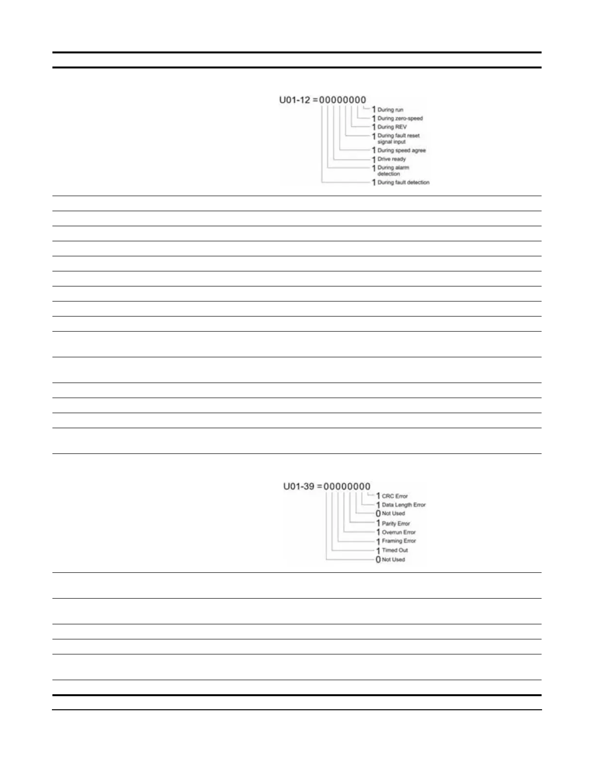
U01-12 Int Ctl Sts 1 Operation Status -
U01-14 CPU 1 SW Number Firmware version -
U01-15 Term A1 Level External Terminal Input level %
U01-16 Term A2 Level External Terminal Input level %
U01-17 Term A3 Level External Terminal Input level %
U01-20 SFS Output Primary freq. after the SFS Hz
U01-21 AI Opt Ch1 Level Displays the input voltage to terminal V1 on analog input card AI-A3. %
U01-22 AI Opt Ch2 Level Displays the input voltage to terminal V2 on analog input card AI-A3. %
U01-23 AI Opt Ch3 Level Displays the input voltage to terminal V3 on analog input card AI-A3. %
U01-24 Opt Out Displays the output from the option card S4IO - 8 bits. -
U01-25 Opt In Low Displays the reference value input from the DI option card (DI-A3,
S4I, or S4IO) lower 8 bits.
-
U01-26 Opt In High Displays the reference value input from the DI option card (DI-A3,
S4I, or S4IO) upper 8 bits.
-
U01-28 CPU 2 SW Number ROM ID -
U01-29 Load Weight Monitors load weight when C10-01 is enabled C10-06
U01-30 SS Delta Speed Snap Shaft Delta Speed between Ch1 and Ch2 after gear ratio Hz
U01-34 OPE Error Code Displays the parameter number that caused the OPExx or Err
(EEPROM write error) error.
-
U01-39 Transmit Error Displays the contents of a Modbus error -
U01-44 ASR Out w/o Filter Output monitor from Speed Control loop (Primary Delay filter input
value). 100% is displayed at motor rated secondary current.
%
U01-50 Hook Height Percentage of Hook height is displayed. This will display 0% until
the system is homed.
%
U01-51 Motor Revolution Number of revolutions after Home with respect to Home. Revs
U01-52 MaintenanceTimer Hours since last timer reset. Hrs
U01-53 Index Count Number of motor revolutions the shaft has moved since the
beginning of a new Index command.
Revs
U01-54 Term RP Inp Freq Displays the frequency of pulse train input terminal RP. Hz
Parameter Display Function Units

 Loading...


