5-4
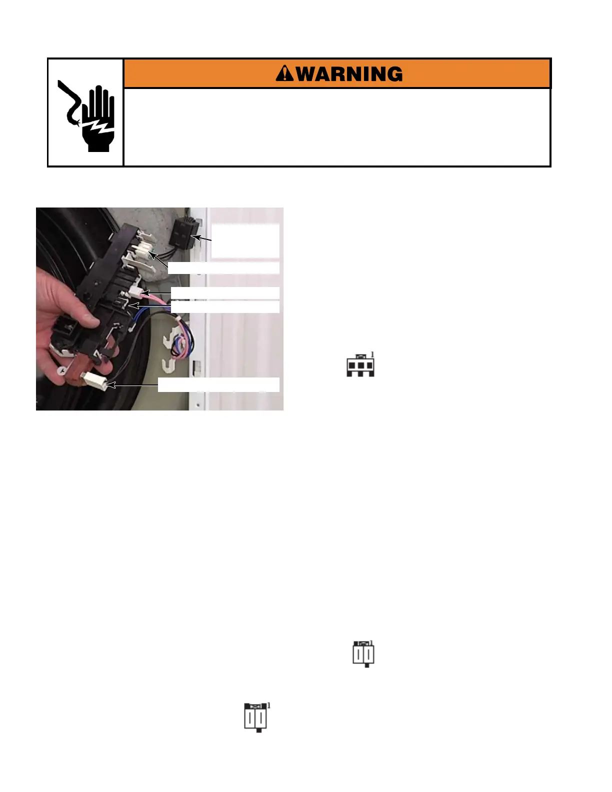
DOOR LOCK ASSEMBLY
Electrical Shock Hazard
Disconnect power before servicing.
Replace all parts and panels before operating.
Failure to do so can result in death or electrical shock.
See page 4-59 for the procedure for
accessing the door lock assembly.
To check the door switch at the CCU, perform
the following steps.
1. Unplug washer or disconnect power.
2. Disconnect the Door Locked Switch
(Locked/Unlocked), connector DLS2
(See page 4-63) from the CCU.
3. Set the ohmmeter to the R X 1 scale.
4. To test the Door Locked Switch, touch the
ohmmeter test leads to pins 1 and 2 on
connector DLS2. The meter should indicate
as follows:
Door locked = Continuity
Door unlocked = No Continuity
5. Disconnect the Door Lock Coil (Locked or
Unlocked), connector DL3
(See page 4-63) from the CCU.
6. To test the Door Lock Coil, touch the
ohmmeter test leads to pins shown below at
DL3. The meter should indicate as follows:
Pins 1 and 2 (Door Lock) = 165Ω
Pins 2 and 3 (Door Unlock) = 165Ω
Abnormal = open circuit (infinite Ω)
7. To test the Wax Motor perform the following
steps.
1. Unplug washer or disconnect power.
2. Disconnect the Wax Motor connector
RP2 (See page 4-63) from the CCU.
3. Set the ohmmeter to the R X 100 scale.
4. Touch the ohm meter test leads to pins 1
and 2 on connector RP2. The meter should
indicate as follows:
Pins 1 and 2 = 1.2kΩ at 77°F
Abnormal = open circuit (infinite Ω)
Wax Motor Connector
Door Closed Switch
Door Locked Switch
Door Lock Solenoid
Ferrite Core
Resistor
Connector DLS2 at CCU
Connector DL3 at CCU
Connector RP2 at CCU