4-44
1. Remove the control panel bracket
(See page 4-8).
2. Use a flat blade screwdriver to lift the
locking tab and disconnect the wire
connector from each coil (See page 4-43).
3. Lift the locking tabs and disconnect the wire
connector to the ignitor (See page 4-41).
4. Disconnect two spade wire connectors from
the radiant sensor (See page 4-41).
5. Remove two 1/4” hex head screws securing
the brace to the bottom of the dryer.
6. Remove the brace by twisting the top tab
out from under the coils.
7. Turn off the gas valve by turning the shutoff
valve, attached to the union, 1/4 turn
counter clockwise.
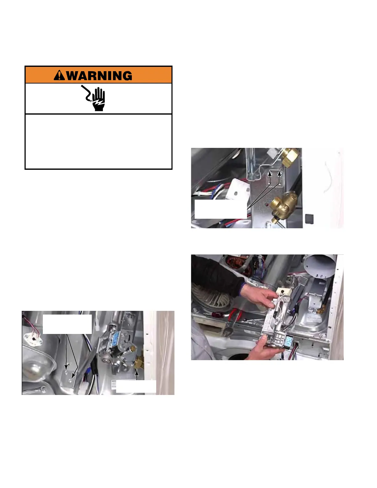
GAS BURNER ASSEMBLY
Two 1/4” Hex
Head Screws
Gas Line
Electrical Shock Hazard
Disconnect power before servicing.
Replace all parts and panels before
operating.
Failure to do so can result in death or
electrical shock.
8. Use a 25mm (1”) open end wrench on the
gas line union to remove gas line from the
valve.
NOTE: From the front of the dryer the
wrench will need to be lifted up to loosen
the nut, because it is reverse threaded.
9. Remove two 1/4” hex head screws under
the bracket securing the gas valve bracket.
10. Slide gas burner assembly out of burner
cone. Make sure not to bump the ignitor.
11. When reinstalling the gas burner
assembly, make sure the tab is inserted into
the slot in the top of the bracket.
NOTE: The gas burner assembly part
number is on a sticker on the bottom of the
assembly. Below the gas burner assembly
is a wire connector with a blue circular
object plugged in. This is an MOV, metal
oxide varister. This filter keeps electrical
noise, caused by the gas valve coils, from
interfering with operation of control board.
Two 1/4” Hex
Head Screws