4-7
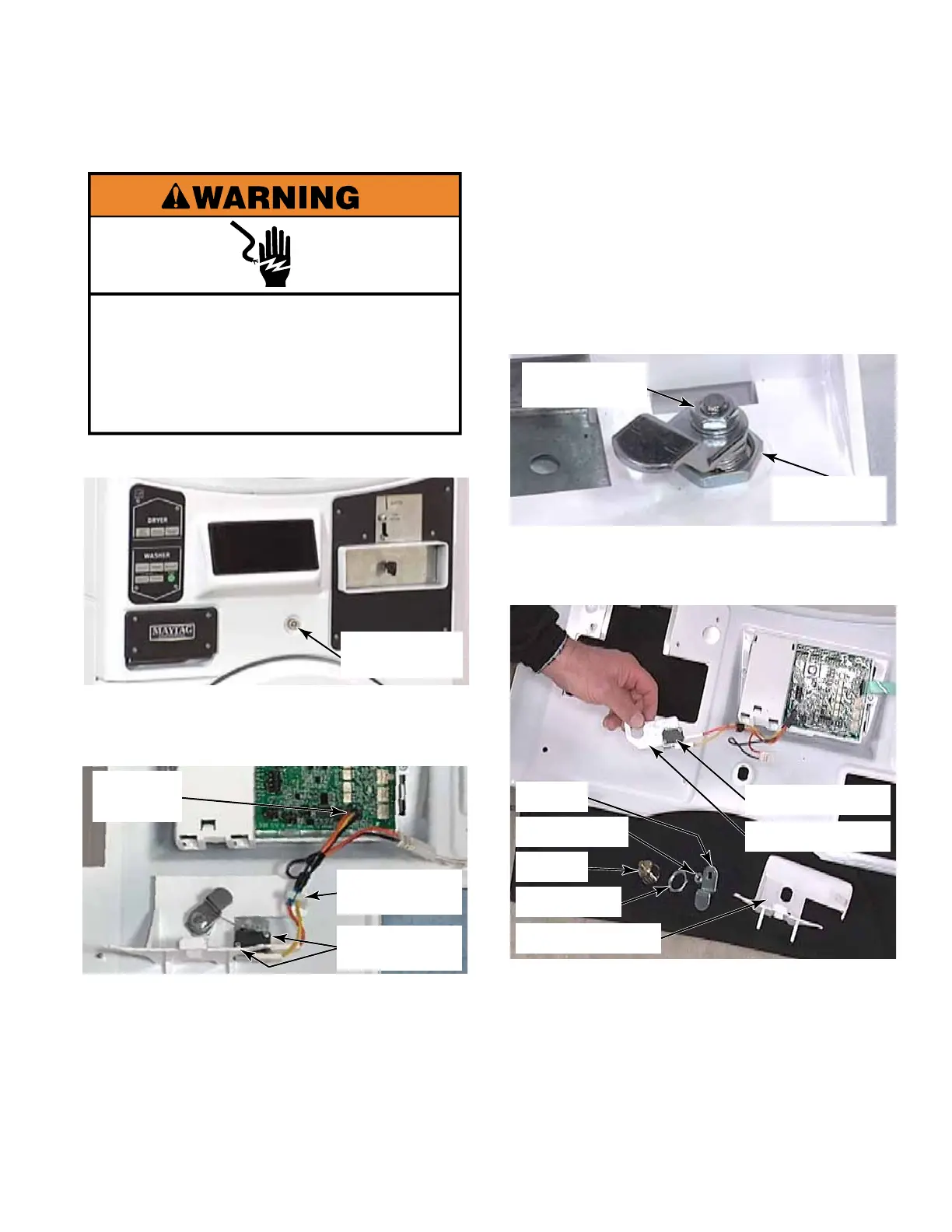
5. To remove the service switch cam and
lock, remove the 11mm (7/16”) nut and star
washer securing the cam to the lock shaft.
Remove the service switch cam from the
shaft.
6. Remove the retainer nut securing lock to
the control panel assembly. Remove lock
from the front of the control panel cover.
7. Remove the switch bracket assembly and
plastic bracket with hook that allows control
panel to be hooked in the service position.
TECH TIP: When reassembling the service
switch assembly, place the metal switch
bracket against the control panel, and
then the plastic bracket on top of the metal
bracket.
Cam
Retainer Nut
Lock
Lock Nut
Metal Bracket
Plastic Bracket
Service Switch
1. Open the control panel (See page 4-3).
2. From inside the control panel, press the
locking tab and disconnect the wire harness
to the service switch from the control board.
3. Remove two #1 Phillips head screws
securing the switch to the bracket.
4. Remove the service switch wires from the
retainer clip and remove the switch with the
wire harness attached.
Service Switch
Assembly
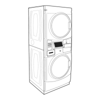
SERVICE SWITCH ASSEMBLY
Electrical Shock Hazard
Disconnect power before servicing.
Replace all parts and panels before
operating.
Failure to do so can result in death or
electrical shock.
Wire
Harness
Two #1 Phillips
Screws
Wire Retainer
Clip
11mm Nut &
Star Washer
Lock
Retainer Nut