2
4
6
8
0
2 4
6 8
64Z8018
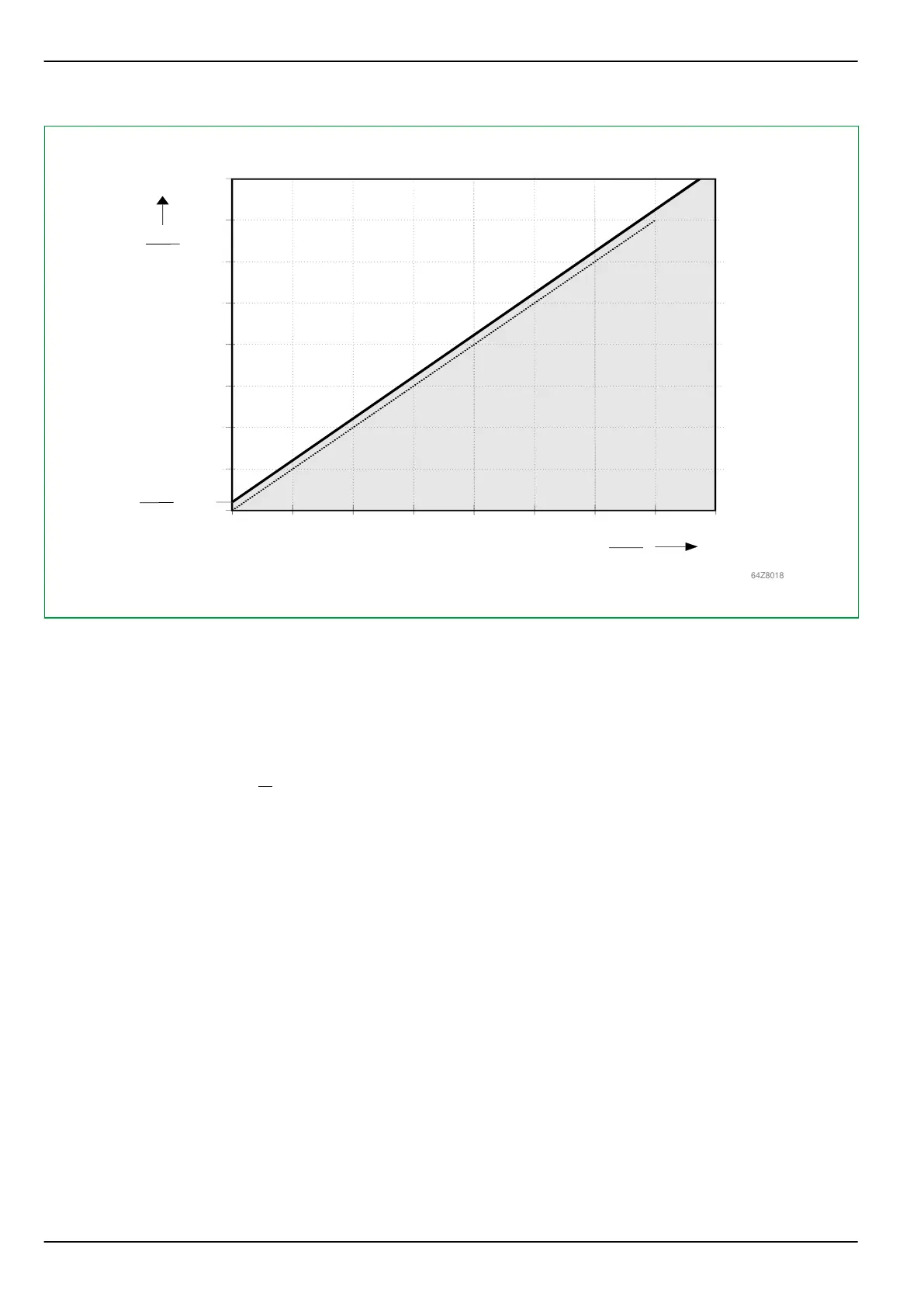
= 0.2
Id,N>
Iref
Id,N
Iref
m = 1.005
IR,N
Iref
Tripping area
Blocking area
Fault current characteristic for transient saturation of the main current transformers
Fig. 3-101: Tripping characteristic of ground differential protection with the “Low imped. / sum(IP)” operating mode
3.22.4.2 “Low imped. / IP,max” Operating Mode
Using this operating mode differential current Id and restraining current IR are
defined as follows:
I
d
=
|
k
am,P
⋅ ∑
{
I
A
, I
B
, I
C
}
+ k
am,Y
⋅ I
Y
|
I
R
=
1
2
⋅
(
k
am,P
⋅ max
{ |
I
A
|
,
|
I
B
|
,
|
I
C
| }
+ k
am,Y
⋅
|
I
Y
| )
When compared to the “Low imped. / sum(IP)” operating mode, a double slope
tripping characteristic can be used here because of the definition of the
restraining current (see Fig. 3-102, (p. 3-147)). In particular, this tripping
characteristic permits a tripping test under load current by shorting a phase
current (to simulate residual current) without the need of star point current I
Y
.
Besides the I
diff>
parameter, already available to set the basic pick-up sensitivity,
the following parameters are also provided with the “Low imped. / IP,max”
operating mode to set the tripping characteristic; in this case I
R,m2
is equivalent
to I
ref
.
P634
3 Operation
3-146 P634/EN M/R-42-A // P634‑311‑653