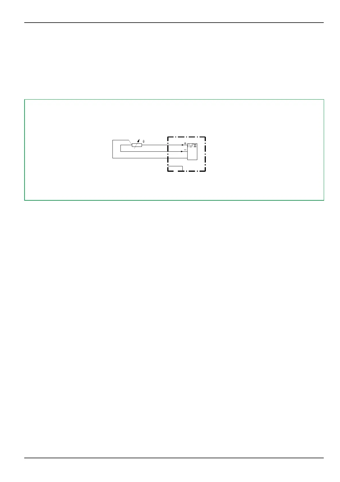
5.6.1.4 Connecting a Resistance Thermometer
A resistance thermometer can be connected if the device is fitted with analog
module Y. This analog I/O module input is designed to connect a PT 100
resistance thermometer. The PT 100 should be connected using the 3-wire
method (see Fig. 5-10, (p. 5-15)). No supply conductor compensation is
required in this case.
S8Z52H9A
PT 100
P634
Fig. 5-10: Connecting a PT 100 using the 3-wire method.
5.6.1.5 Connecting Binary Inputs and Output Relays
The binary inputs and output relays are freely configurable. When configuring
these components it is important to note that the contact rating of the binary I/O
modules (X) varies (see Section 2.5.7, (p. 2-13)).
The polarity for connected binary signal inputs is to be found in the terminal
connection diagrams (see supporting documents supplied with the device or in
Section 5.7, (p. 5-22)). This is to be understood as a recommendation only.
Connection to binary inputs can be made as desired.
5.6.1.6 Connecting Trip and Close Command Relays
Standard outputs of Px30 aren't supposed to open DC current flowing through
inductive CB coil. This task has to be addressed by properly applied CB auxiliary
contacts (52a/b).
5 Installation and Connection P634
P634/EN M/R-42-A // P634‑311‑653 5-15