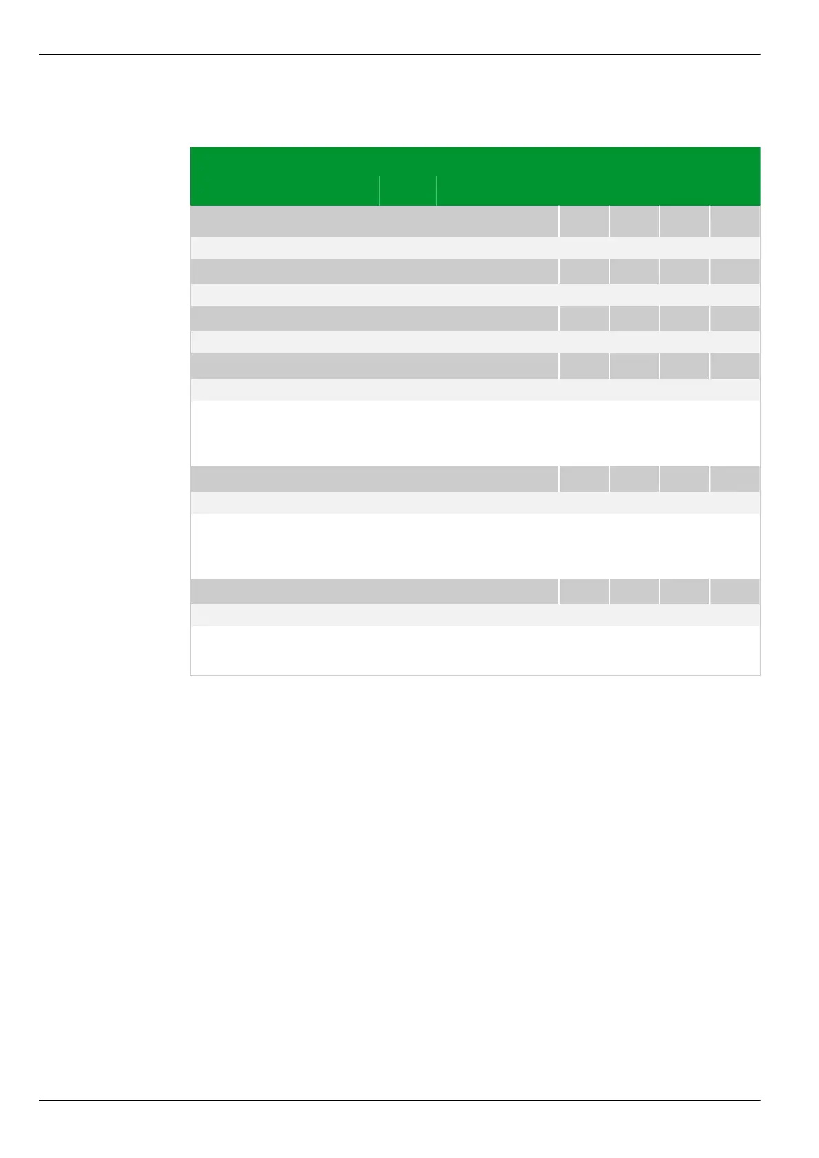
7.1.3.2 General Functions
Parameter Address
Default Min Max Unit Logic Diagram
Main function
MAIN: Evaluation IN, end a
016 096
1: Calculated Fig. 3-43, (p. 3-72)
[spacer]
MAIN: Evaluation IN, end b
016 097
1: Calculated Fig. 3-43, (p. 3-72)
[spacer]
MAIN: Evaluation IN, end c
016 098
1: Calculated Fig. 3-43, (p. 3-72)
[spacer]
MAIN: Evaluation IN, end d
016 099
1: Calculated
[spacer]
This setting specifies which current will be used by the P634 as the residual
current: either the calculated residual current derived from the sum of the phase
currents or the residual current measured at the fourth transformer.
[spacer]
MAIN: Current summation
019 099
0: Without Fig. 3-44, (p. 3-74)
[spacer]
For two ends of the transformer, the currents for each phase and the residual
currents can be combined. This setting specifies the transformer ends to be
involved.
[spacer]
MAIN: Hold time dyn.param.
018 009
Blocked 0.00 100.00 s Fig. 3-56, (p. 3-88)
[spacer]
Setting for the hold time of the “dynamic parameters”. During this period, the
“dynamic” thresholds are active in place of the “normal” thresholds.
P634 7 Settings
7-84 P634/EN M/R-42-A // P634‑311‑653