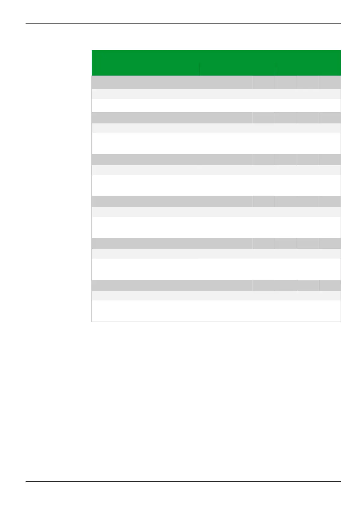
Parameter Address
Default Min Max Unit Logic Diagram
Fault recording
FT_RC: Fct. assig. trigger
003 085
060 000: MAIN: Without function Fig. 3-82, (p. 3-119)
[spacer]
This setting defines the signals that will trigger fault recording.
[spacer]
FT_RC: Id>
016 018
Blocked 0.01 30.00 Iref
[spacer]
This setting defines the threshold value of the differential current that will
trigger disturbance recording.
[spacer]
FT_RC: IR>
016 019
Blocked 0.01 30.00 Iref
[spacer]
This setting defines the threshold value of the restraining current that will
trigger fault recording.
[spacer]
FT_RC: Pre-fault time
003 078
5 1 50 Periods Fig. 3-84, (p. 3-122)
[spacer]
Setting for the time during which data will be recorded before the onset of a
fault (pre-fault recording time).
[spacer]
FT_RC: Post-fault time
003 079
2 1 50 Periods Fig. 3-84, (p. 3-122)
[spacer]
Setting for the time during which data will be recorded after the end of a fault
(post-fault recording time).
[spacer]
FT_RC: Max. recording time
003 075
50 5 300 Periods Fig. 3-84, (p. 3-122)
[spacer]
Setting for the maximum recording time per fault. This includes pre-fault and
post-fault recording times.
7 Settings P634
P634/EN M/R-42-A // P634‑311‑653 7-83