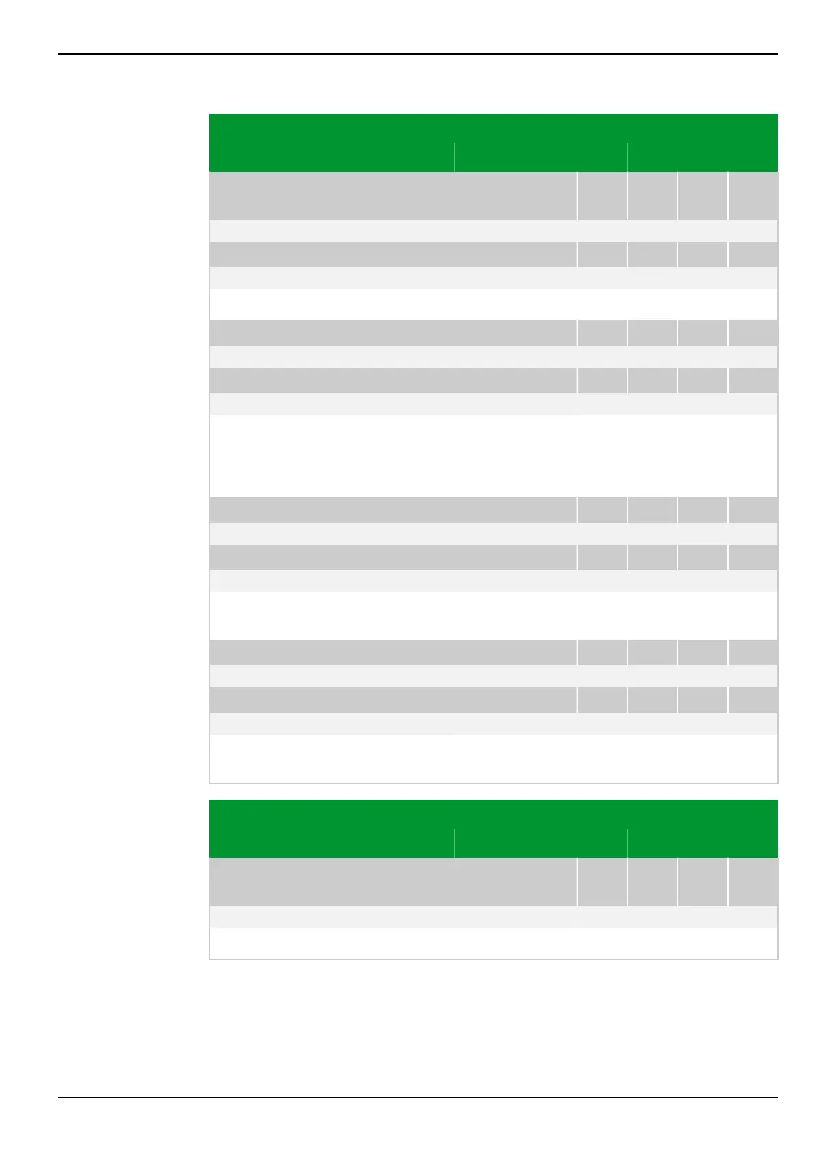
Parameter Address
Default Min Max Unit Logic Diagram
Thermal overload
protection
THRM1: General enable USER
031 144
0: No Fig. 3-127, (p. 3-174)
[spacer]
THRM2: General enable USER
031 145
0: No
[spacer]
Disabling and enabling the thermal overload protection function.
[spacer]
THRM1: Select. meas. input
019 109
1: End b Fig. 3-129, (p. 3-176)
[spacer]
THRM2: Select. meas. input
019 110
2: End c
[spacer]
Selection of the current relevant for thermal overload protection. Select from the
currents measured at the measuring input for end a, b, c, d. There is an
additional option, namely the selection of the value obtained according to the
setting at MAIN: Current summation.
[spacer]
THRM1: Operating mode
039 121
2: Relative replica Fig. 3-132, (p. 3-180)
[spacer]
THRM2: Operating mode
039 181
2: Relative replica
[spacer]
Setting for the operating mode of thermal overload protection. Select between
Absolute replica and Relative replica.
[spacer]
THRM1: O/T f.Iref persist 1
004 152
Not measured -40 300 °C
[spacer]
THRM2: O/T f.Iref persist 2
004 172
Not measured -40 300 °C
[spacer]
Display of the difference between the settings for the maximum permissible
temperatures of the protected object and the coolant.
Parameter Address
Default Min Max Unit Logic Diagram
Time-voltage protec‐
tion
V<>: General enable USER
023 030
0: No Fig. 3-134, (p. 3-182)
[spacer]
Disabling or enabling time-voltage protection.
7 Settings P634
P634/EN M/R-42-A // P634‑311‑653 7-91