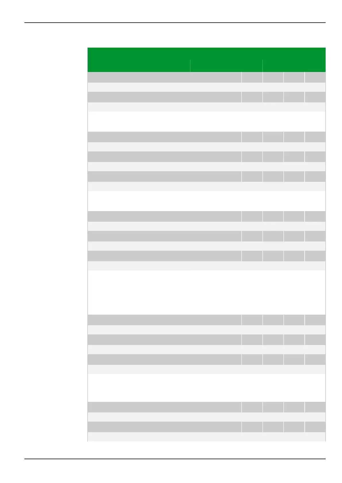
Parameter Address
Default Min Max Unit Logic Diagram
[spacer]
REF_2: Idiff> PSx
072 170 073 170 074 170 075 170
0.20 0.10 1.00 Iref
[spacer]
REF_3: Idiff> PSx
072 040 073 040 074 040 075 040
0.20 0.10 1.00 Iref
[spacer]
Operate value of the ground differential protection function as referred to the
reference current of the relevant transformer end.
[spacer]
REF_1: Idiff>>> PSx
072 151 073 151 074 151 075 151
10.0 2.5 30.0 Iref Fig. 3-103, (p. 3-148)
[spacer]
REF_2: Idiff>>> PSx
072 171 073 171 074 171 075 171
10.0 2.5 30.0 Iref
[spacer]
REF_3: Idiff>>> PSx
072 041 073 041 074 041 075 041
10.0 2.5 30.0 Iref
[spacer]
Threshold value of the differential current for tripping by the ground differential
protection function independently of the restraining variable.
[spacer]
REF_1: m1 PSx
072 162 073 162 074 162 075 162
0.20 0.00 1.00 Fig. 3-103, (p. 3-148)
[spacer]
REF_2: m1 PSx
072 172 073 172 074 172 075 172
0.20 0.00 1.00
[spacer]
REF_3: m1 PSx
072 192 073 192 074 192 075 192
0.20 0.00 1.00
[spacer]
Gradient of the differential protection tripping characteristic with the operating
mode 'Low imped. / sum(IP)'.
Gradient of the differential protection tripping characteristic for the
range I
R
< I
R,m1
with the operating modes 'Low imped. / IP,max ' and 'High
impedance'.
[spacer]
REF_1: m2 PSx
072 163 073 163 074 163 075 163
1.50 0.15 1.50 Fig. 3-103, (p. 3-148)
[spacer]
REF_2: m2 PSx
072 165 073 165 074 165 075 165
1.50 0.15 1.50
[spacer]
REF_3: m2 PSx
072 193 073 193 074 193 075 193
1.50 0.15 1.50
[spacer]
Gradient of the differential protection tripping characteristic for the
range I
R
> I
R,m2
with the operating modes 'Low imped. / IP,max ' and 'High
impedance'.
[spacer]
REF_1: IR,m2 PSx
072 164 073 164 074 164 075 164
1.00 0.10 1.50 Iref Fig. 3-103, (p. 3-148)
[spacer]
REF_2: IR,m2 PSx
072 166 073 166 074 166 075 166
1.00 0.10 1.50 Iref
7 Settings P634
P634/EN M/R-42-A // P634‑311‑653 7-155
 Loading...
