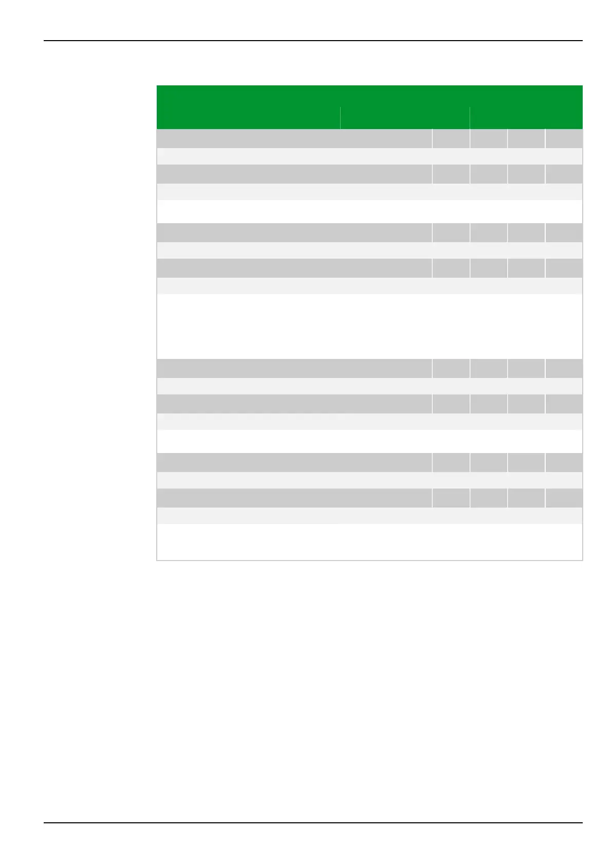
Parameter Address
Default Min Max Unit Logic Diagram
[spacer]
THRM1: Rel. O/T warning PSx
081 079 082 079 083 079 084 079
95 50 200 % Fig. 3-132, (p. 3-180)
[spacer]
THRM2: Rel. O/T warning PSx
081 099 082 099 083 099 084 099
95 50 200 %
[spacer]
Setting for the operate value of the warning stage.
[spacer]
THRM1: Rel. O/T trip PSx
081 076 082 076 083 076 084 076
100 50 200 % Fig. 3-132, (p. 3-180)
[spacer]
THRM2: Rel. O/T trip PSx
081 096 082 096 083 096 084 096
100 50 200 %
[spacer]
Setting for the operate value of the trip stage.
Note: If the operating mode has been set to Absolute replica, the setting here
will be automatically set to 100% and this parameter will be hidden as far as the
local control panel is concerned.
[spacer]
THRM1: Hysteresis trip PSx
081 078 082 078 083 078 084 078
2 2 30 % Fig. 3-132, (p. 3-180)
[spacer]
THRM2: Hysteresis trip PSx
081 098 082 098 083 098 084 098
2 2 30 %
[spacer]
Setting for the hysteresis of the trip stage.
[spacer]
THRM1: Warning pre-trip PSx
081 085 082 085 083 085 084 085
30.0 0.0 1000.0 min Fig. 3-132, (p. 3-180)
[spacer]
THRM2: Warning pre-trip PSx
081 105 082 105 083 105 084 105
30.0 0.0 1000.0 min
[spacer]
A warning will be given in advance of the trip. The time difference between the
warning time and the trip time is set here.
7 Settings P634
P634/EN M/R-42-A // P634‑311‑653 7-175
 Loading...
