Parameter Address
Default Min Max Unit Logic Diagram
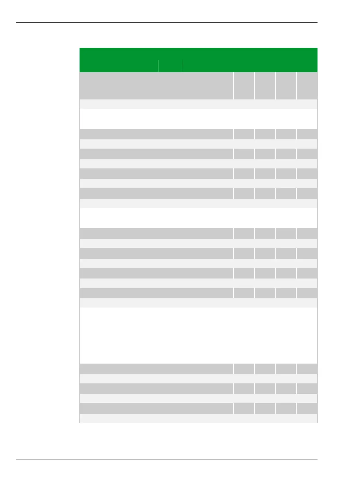
Over-/
underfrequency pro‐
tection
f<>: Enable PSx
018 196 018 197 018 198 018 199
0: No Fig. 3-137, (p. 3-185)
[spacer]
This setting defines the parameter subset in which over-/underfrequency
protection is enabled.
[spacer]
f<>: Oper. mode f1 PSx
018 120 018 121 018 122 018 123
1: f Fig. 3-140, (p. 3-188)
[spacer]
f<>: Oper. mode f2 PSx
018 144 018 145 018 146 018 147
1: f
[spacer]
f<>: Oper. mode f3 PSx
018 168 018 169 018 170 018 171
1: f
[spacer]
f<>: Oper. mode f4 PSx
018 192 018 193 018 194 018 195
1: f
[spacer]
Setting for the operating mode of the timer stages of over-/underfrequency
protection.
[spacer]
f<>: f1 PSx
018 100 018 101 018 102 018 103
49.80 40.00 70.00 Hz Fig. 3-140, (p. 3-188)
[spacer]
f<>: f2 PSx
018 124 018 125 018 126 018 127
49.80 40.00 70.00 Hz
[spacer]
f<>: f3 PSx
018 148 018 149 018 150 018 151
49.80 40.00 70.00 Hz
[spacer]
f<>: f4 PSx
018 172 018 173 018 174 018 175
49.80 40.00 70.00 Hz
[spacer]
Setting for the frequency threshold. The over-/underfrequency protection
function will operate if one of the following two conditions applies: The
threshold is higher than the set nominal frequency and the frequency exceeds
this threshold. The threshold is lower than the set nominal frequency and the
frequency falls below this threshold. Depending on the chosen operating mode,
either a signal is issued without further monitoring, or further monitoring
mechanisms are started.
[spacer]
f<>: tf1 PSx
018 104 018 105 018 106 018 107
0.00 0.00 10.00 s Fig. 3-140, (p. 3-188)
[spacer]
f<>: tf2 PSx
018 128 018 129 018 130 018 131
0.00 0.00 10.00 s
[spacer]
f<>: tf3 PSx
018 152 018 153 018 154 018 155
0.00 0.00 10.00 s
P634 7 Settings
7-178 P634/EN M/R-42-A // P634‑311‑653