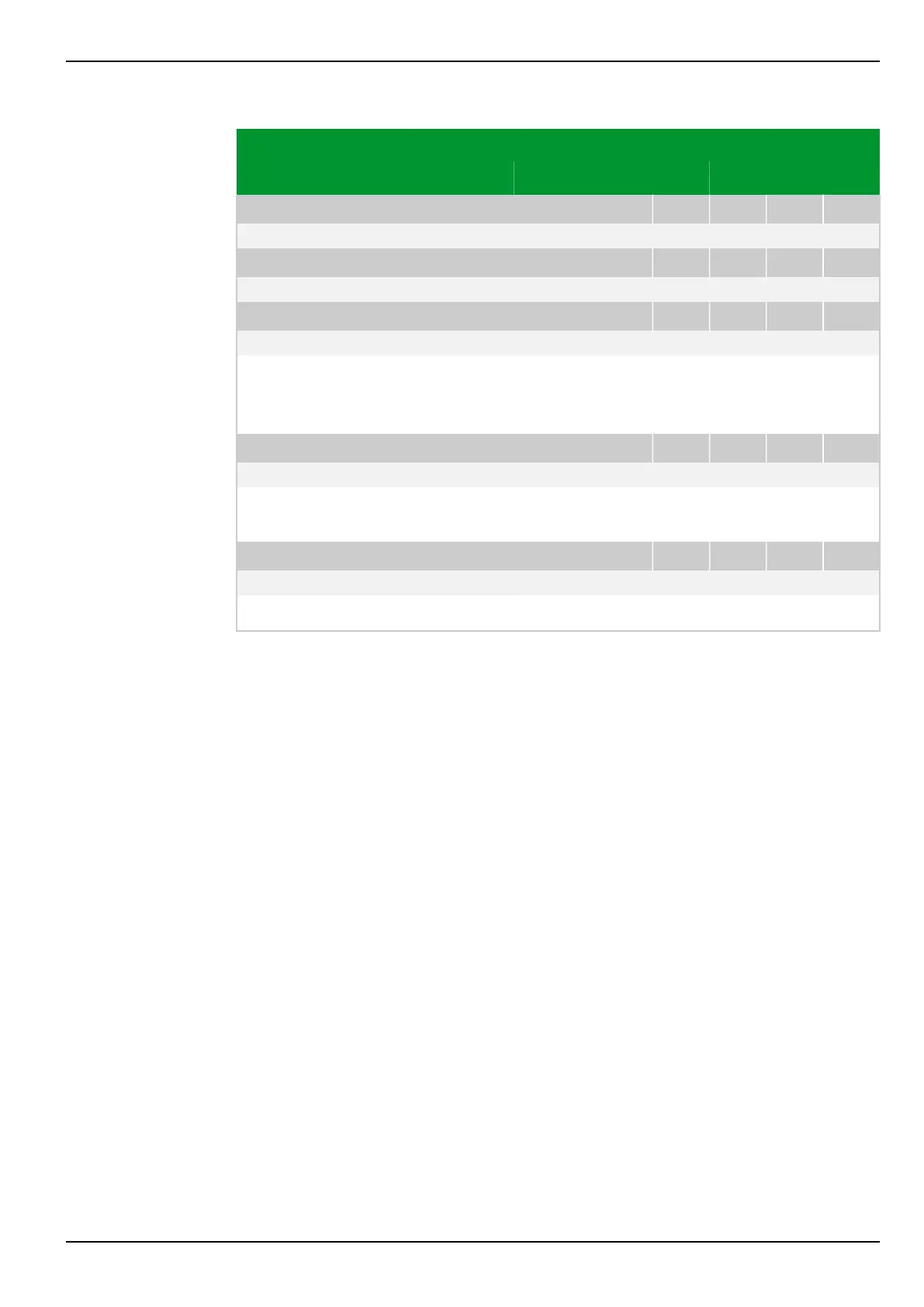
Parameter Address
Default Min Max Unit Logic Diagram
[spacer]
V/f: t at V/f=1.50 PSx
081 226 082 226 083 226 084 226
1.5 1.0 6000.0 s Fig. 3-147, (p. 3-194)
[spacer]
V/f: t at V/f=1.55 PSx
081 227 082 227 083 227 084 227
1.4 1.0 6000.0 s Fig. 3-147, (p. 3-194)
[spacer]
V/f: t at V/f=1.60 PSx
081 228 082 228 083 228 084 228
1.3 1.0 6000.0 s Fig. 3-147, (p. 3-194)
[spacer]
The value pairs set here for overfluxing and trip time define the tripping
characteristic of the inverse-time trip stage for overfluxing protection.
The value set at V/f = 1.60 is also valid for V/f > 1.60.
[spacer]
V/f: Reset time PSx
081 230 082 230 083 230 084 230
0 0 60000 s Fig. 3-147, (p. 3-194)
[spacer]
The value set here for the reset time defines the decreasing rate for the
overfluxing protection memory.
[spacer]
V/f: tV/f>> PSx
081 229 082 229 083 229 084 229
Blocked 0 10000 s Fig. 3-144, (p. 3-191)
[spacer]
Setting for the operate delay of the definite-time trip stage.
7 Settings P634
P634/EN M/R-42-A // P634‑311‑653 7-181