Parameter Address
Default Min Max Unit Logic Diagram
[spacer]
INP: State U 1805
194 017
0: "Low"
[spacer]
INP: State U 1806
194 021
0: "Low"
[spacer]
INP: State U 2001
153 086
0: "Low"
[spacer]
INP: State U 2002
153 089
0: "Low"
[spacer]
INP: State U 2003
153 092
0: "Low"
[spacer]
INP: State U 2004
153 095
0: "Low"
[spacer]
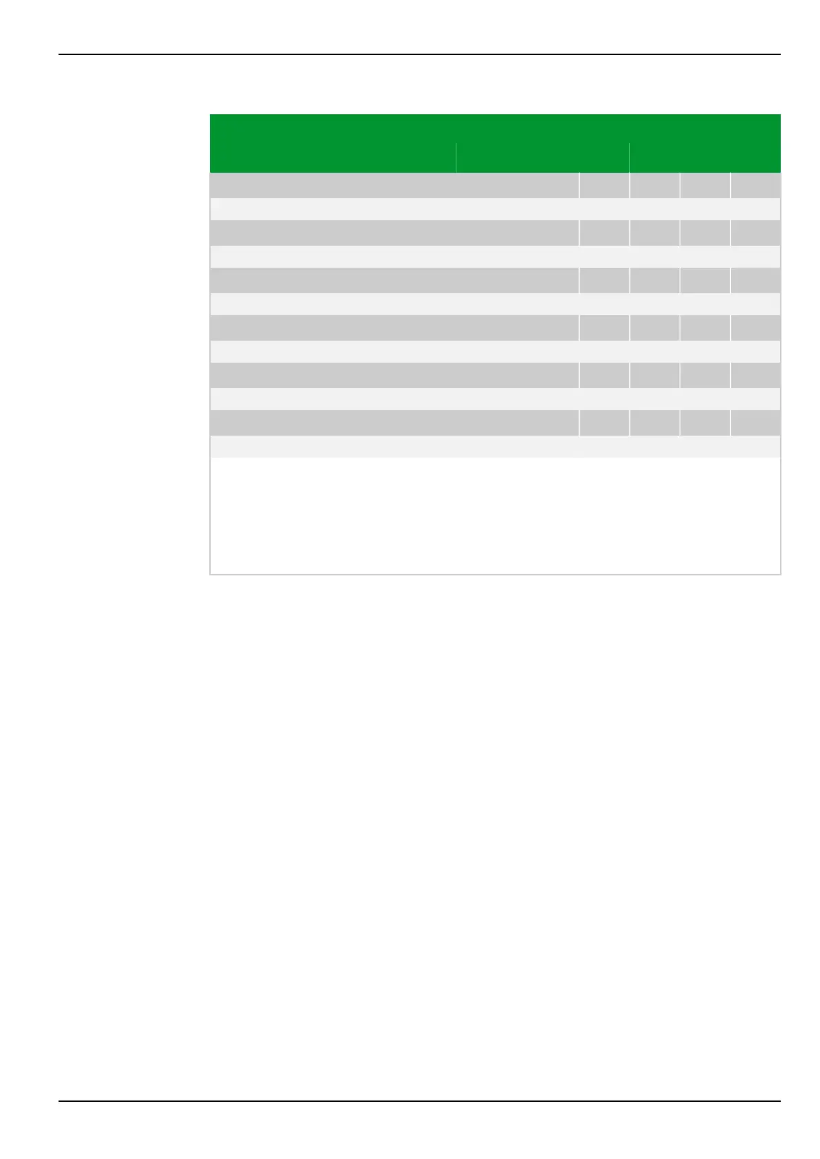
The state of the binary signal inputs is displayed as follows:
●
Without function: No functions are assigned to the binary signal input.
●
"Low": Not energized.
●
"High": Energized.
This display appears regardless of the setting for the binary signal input mode.
8 Information and Control Functions P634
P634/EN M/R-42-A // P634‑311‑653 8-31