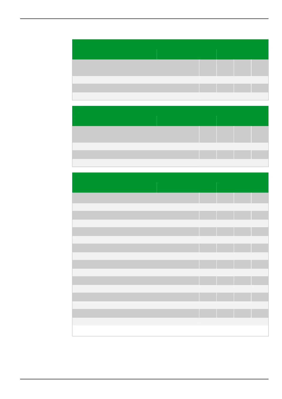
Parameter Address
Default Min Max Unit Logic Diagram
Circuit breaker
failure protection
CBF_3: Enable USER
003 126
0: don't execute
[spacer]
CBF_3: Disable USER
003 125
0: don't execute
Parameter Address
Default Min Max Unit Logic Diagram
Circuit breaker
failure protection
CBF_4: Enable USER
003 128
0: don't execute
[spacer]
CBF_4: Disable USER
003 127
0: don't execute
Parameter Address
Default Min Max Unit Logic Diagram
Programmable Logic
LOGIC: Trigger 1
034 038
0: No Fig. 3-175, (p. 3-221)
[spacer]
LOGIC: Trigger 2
034 039
0: No
[spacer]
LOGIC: Trigger 3
034 040
0: No
[spacer]
LOGIC: Trigger 4
034 041
0: No
[spacer]
LOGIC: Trigger 5
034 042
0: No
[spacer]
LOGIC: Trigger 6
034 043
0: No
[spacer]
LOGIC: Trigger 7
034 044
0: No
[spacer]
LOGIC: Trigger 8
034 045
0: No Fig. 3-175, (p. 3-221)
[spacer]
Intervention in the logic at the appropriate point by a 100 ms pulse.
8 Information and Control Functions P634
P634/EN M/R-42-A // P634‑311‑653 8-159