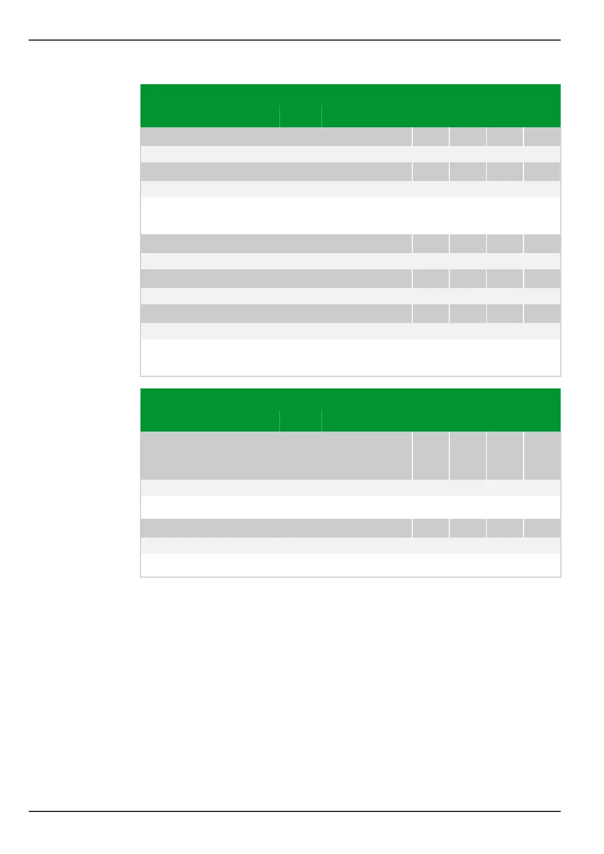
Parameter Address
Default Min Max Unit Logic Diagram
[spacer]
FT_DA: Diff. current REF_2
026 082
Not measured 0.00 99.00 Iref Fig. 3-81, (p. 3-117)
[spacer]
FT_DA: Diff. current REF_3
027 082
Not measured 0.00 99.00 Iref Fig. 3-81, (p. 3-117)
[spacer]
Display of the differential current, determined by the ground differential
protection function (REF_1, REF_2 or REF_3, respectively), referred to I
ref
.
[spacer]
FT_DA: Restrain.curr. REF_1
025 083
Not measured 0.00 99.00 Iref Fig. 3-81, (p. 3-117)
[spacer]
FT_DA: Restrain.curr. REF_2
026 083
Not measured 0.00 99.00 Iref Fig. 3-81, (p. 3-117)
[spacer]
FT_DA: Restrain.curr. REF_3
027 083
Not measured 0.00 99.00 Iref Fig. 3-81, (p. 3-117)
[spacer]
Display of the restraining current, determined by the ground differential
protection function (REF_1, REF_2 or REF_3, respectively), referred to I
ref
.
Parameter Address
Default Min Max Unit Logic Diagram
Over-/
underfrequency pro‐
tection
f<>: Max. frequ. for f>
005 002
Not measured 12.00 70.00 Hz
[spacer]
Maximum frequency during an overfrequency condition.
[spacer]
f<>: Min. frequ. for f<
005 001
Not measured 12.00 70.00 Hz
[spacer]
Minimum frequency during an underfrequency condition.
P634 8 Information and Control Functions
8-168 P634/EN M/R-42-A // P634‑311‑653