PCWS 2015 Setup Guide - 2nd Edition 4-5
Installing and Operating the Workstation 2015
The IO Panel
The IO Panel
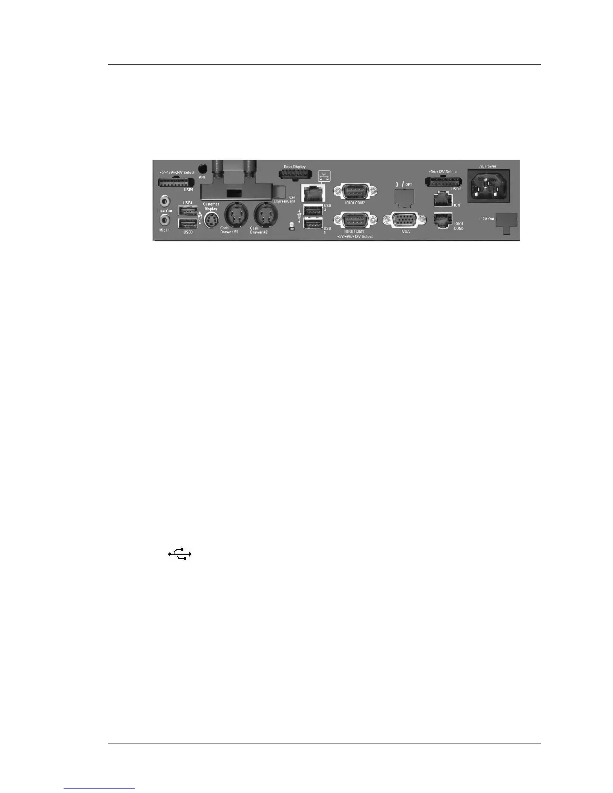
Figure 4-1 shows the PC Workstation 2015 IO Panel layout.
Figure 4-1: The PCWS 2015 I/O Panel
Working from left to right in the illustration, each connector is detailed below.
Line Out - Mic In
The Green Line Out connector is an output, capable of driving external
powered speakers. The internal speakers are still active when this output is
used.
The Mic In jack allows you to connect a microphone to record sound clips.
Windows Embedded CE 6.0 configurations do not include sound recording
software.
+5V/+12V/+24V Select - USB5
The USB5 connector combines a USB 2.0 compatible interface with either
+5V, +12V or +24V.
Three optional dongles are available, one for each voltage. Each dongle
terminates with a standard Powered USB connector identified by its color. For
example, to use a powered USB Printer that requires +24V, a +24V dongle
must be purchased.
USB1 - USB4
The PCWS 2015 includes four standard Type A USB 2.0 compatible ports,
labeled USB1 through USB4. When the unit it shipped, all ports are enabled.
For PCI-DSS compliance, all I/O Panel USB Ports (including USB5 and
USB6) can be disabled through the BIOS.
Customer Display
This 4-pin mini-din connector supports either a stand or pole mount LCD
Customer Display. See Chapter 1 for more information about optional
customer displays.