3-22 PCWS 2015 Setup Guide - 2nd Edition
What’s Inside?
System Board Description
SW3 - Recovery Button
SW3 is used to start Factory Recovery. See Chapter 4 for more information.
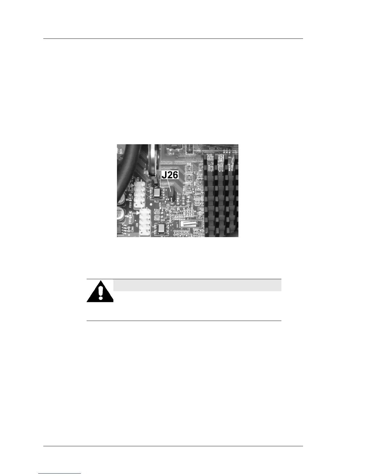
J26 - CMOS Clear (Revision C and D)
J26 clears the CMOS memory, but does not clear the system time/date.
However, clearing the CMOS re-enables all default settings including IO Panel
USB ports that may have been disabled for PCI-DSS compliance.
J26 is a 1x2 header. Workstations are shipped with the header installed in a
‘park’ (inactive) position as shown in the Figure below.
Figure 3-23: J26 - CMOS Clear Jumper (Inactive Position)
1. Remove the AC Power Cable from the workstation! This is required to
remove all standby voltages from the RTC circuitry.
2. Move the jumper from the inactive position to pins 1-2 for a few seconds,
then move the jumper back to the inactive position.
o If the AC power cable remains connected, the unit may power up at this
point. To avoid damage, remove power from the board immediately.
3. Connect a USB Keyboard and AC power cable to the workstation.
4. If the unit does not start when the AC power cable is reconnected, press the
power button to start the unit. When the Blue splash screen appears, press
[F2] to enter the BIOS Configuration screen.
o Refer to Chapter 3 to selectively disable USB Ports USB1 through
USB6 as required.
WARNING: Hazard to Equipment
Failure to remove the AC Power Cable from the unit
when using J26 could result in damage to the System
Board.