1-8 PCWS 2015 Setup Guide - 2nd Edition
What is the PCWS 2015
Features
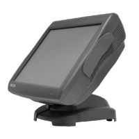
Figure 1-3 shows the proprietary Powered USB implementation with a six
foot custom powered USB Cable connected between the workstation and
the USB module of the Epson TM- T88V thermal printer.
Figure 1-3: Powering the TM-T88V from the optional +24V Powered USB Dongle
+5V and +12V Powered USB Dongles are also available. See the
Specifications page for more details on voltages and available power.
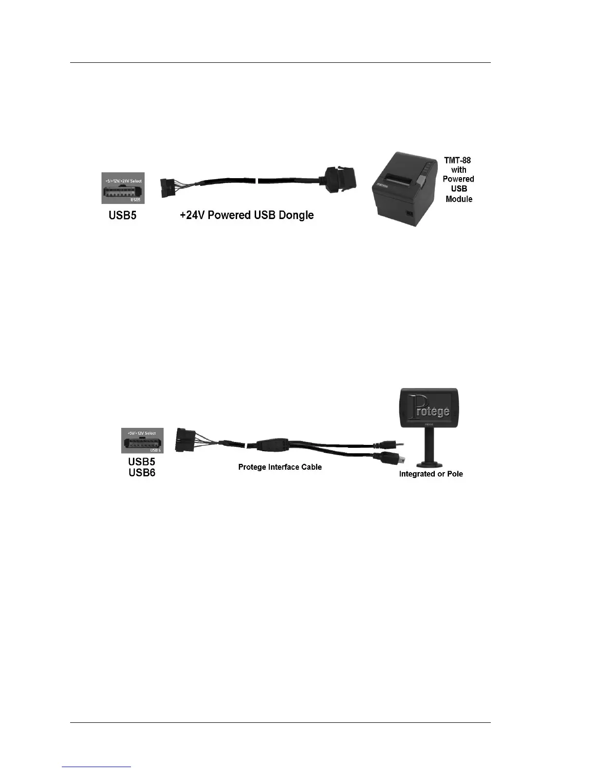
Figure 1-4, below shows the optional MICROS Protege Customer Display
System connected to the USB5 or USB6 ports using a custom cable that
carries both USB port data and +12V to operate a new class of intelligent
USB peripheral devices.
Figure 1-4: MICROS Protege Customer Display Connected USB5 or USB6
System Board USB Headers
A total of seven 2x5 USB headers are located on the System Board. One is
dedicated to the optional eUSB flash drive, and one port is dedicated to the
resistive or capacitive touch controller. This leaves additional headers
available for options such as the integrated biometric fingerprint reader and
or an 802.11 compatible USB WiFi card.
USB Port Security
All IO Panel USB ports can be individually disabled to prevent the use of
keyboards, flash drives or other USB devices. USB per-port control is
currently implemented in the BIOS. Future versions of the 2015 will allow
USB per-port control through the PCWS API.