PCWS 2015 Setup Guide - 2nd Edition 2-33
PCWS 2015 BIOS
Boot
Boot
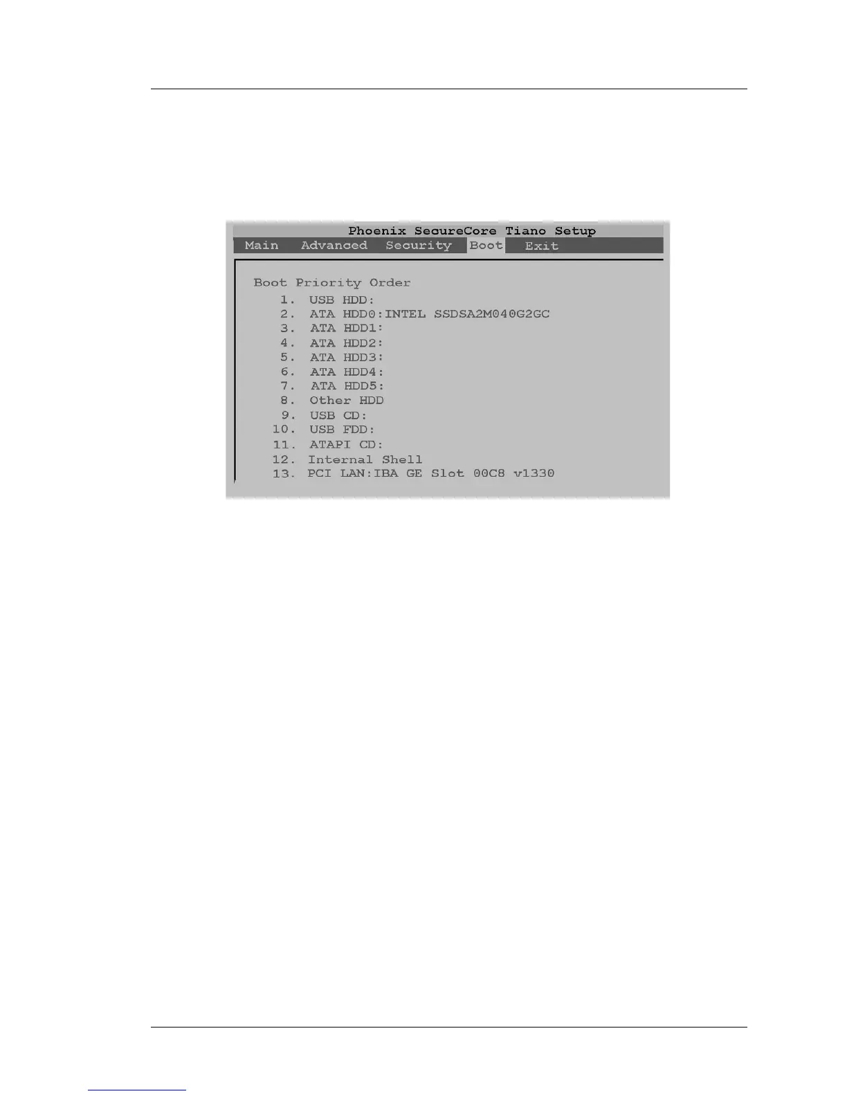
The Boot Tab displays the Boot Priority Order. The default boot order is shown
in Figure 2-19, below.
Figure 2-19: PCWS 2015 BIOS Boot Order
After the Workstation completes POST, the BIOS starts at number 1 in the
Boot Priority List and works its way down, skipping inactive devices until it
finds a device with a boot sector. If no bootable device is found, the BIOS
displays the UEFI Shell, a text screen.
When a device is found, the ID string appears to the right of the device. In the
example shown above, the optional Intel 40GB SSD is installed on ATA
HDD0.
ATA HDD0 - ATA HDD3
The PCWS 2015 supports booting from up to four SATA devices, ATA HDD0
through ATA HDD3. ATA HDD0: and ATA HDD1: are reserved for SATA
drives located in the Drive Bay, while ATA HDD3: supports the SATA CF
Riser Card on Revision C System Boards and ATA HDD2: on Revision D
System Boards.
USB HDD
Refers to a external USB Hard disk or thumb drive connected to an IO Panel
USB Port. If the device is bootable, you can use the [Shift][+] keys to move
USB HDD to the top of the boot order.
In some BIOS versions, the USB HDD field defaults to the top of the boot
order. If a USB thumb drive is installed for backup purposes, the unit may skip
the SATA disk and boot directly from the thumb drive.