PCWS 2015 Setup Guide - 2nd Edition 3-9
What’s Inside?
Disassembling the PCWS 2015
Drive Bay
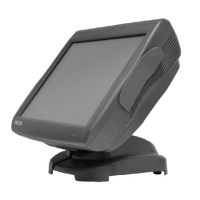
Figure 3-7 shows the PCWS 2015 base with the system board removed to
expose the drive bay. Each drive is installed/removed from access panels on
the bottom of the unit.
The copper bonding process appears as a shiny silver coating on most of the
interior surfaces.
Figure 3-7: PCWS 2015 Drive Bay
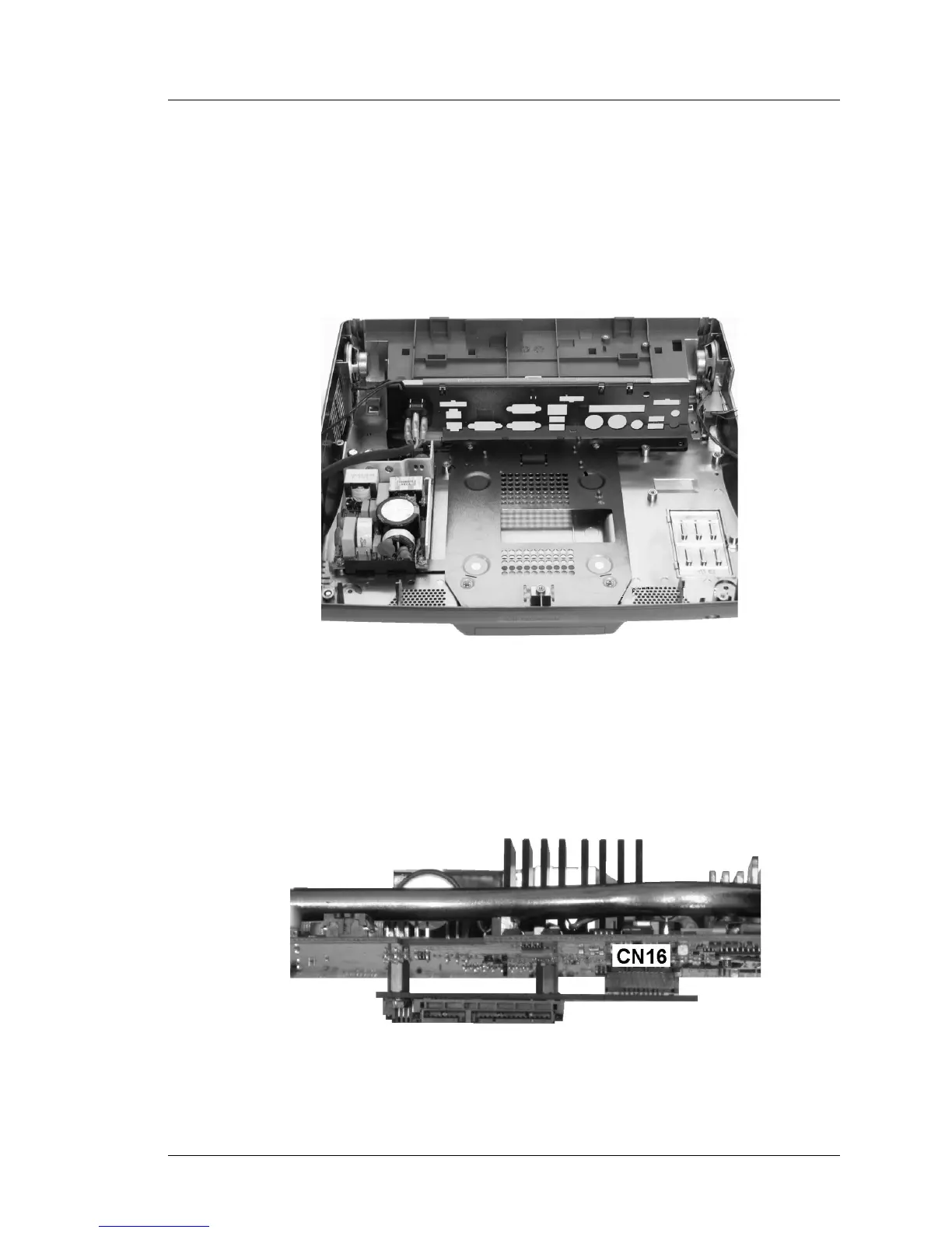
Figure 3-8 is an edge-on view of the system board to illustrate how the SATA
HDD Daughter Card is attached to CN16 on the solder side of the system
board.
Figure 3-8: SATA Daughter Card Attached to the System Board