2-26 PCWS 2015 Setup Guide - 2nd Edition
PCWS 2015 BIOS
Advanced
Special Configuration
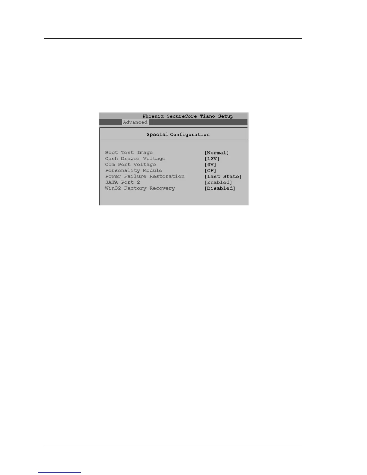
The Special Configuration screen is shown in Figure 2-14, below. It contains
custom BIOS fields specific to the PCWS 2015. This includes settings to
determine the Powered RS232 Voltage, Cash Drawer Voltage or enable the
WIN32 Factory Recovery feature.
Figure 2-14: Special Configuration Menu (BIOS O1301g)
Boot Test Image [Normal]
Enable or Disable the eUSB Hard Drive socket J3. The default selection of
[Normal] causes the BIOS to boot from the USB Flash Drive socket (if
installed).
Setting this field to [Alternate] disables the eUSB Hard Drive by removing
power from socket J3, forcing the BIOS to boot from a removable thumb
drive attached to an IO panel USB Port.
Boot Test Image is used for Windows CE configurations, and is not valid
when used in WIN32 booting from a SATA disk drive or RAID.
Cash Drawer Voltage [12V]
This selection determines the Cash Drawer solenoid voltage. The default
selection of 12V is suitable for all MICROS Cash Drawers.
COM Port Voltage [5V] or [0V]
This selection determines the voltage used by COM1, the Powered RS232
Port on the IO Panel. Selections include 5V, 9V, and 12V.
BIOS Version O1301g or later defaults to 0V.
Personality Module [CF]
This field determines the location of the persistent registry; either the CF or
USB Flash Drive. It is used for Windows CE configurations, and is not
valid when used with WIN32 operating systems.