2-6
NOTE
z Some modules are optional. Their connectors may not be available on your patient
monitor.
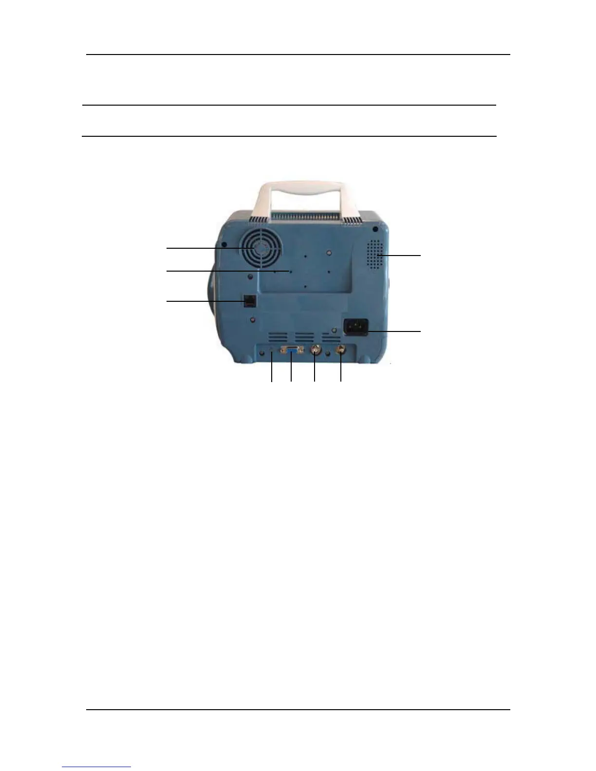
2.2.4 Rear Panel
Figure 2-5 Rear Panel
1. Fan Vent
2. Speaker holes
3. Mounting holes for support bracket.
4. Network Connector: Standard RJ45 connector.
Through network connector, this monitor can be connected with the central monitoring
system, another monitor, or a PC. It enables the functions of viewbed monitoring, data
output and on-line software upgrading.
5. AC Power Input Connector
A three-wire power cord can be connected to this receptacle to provide AC power supply to
the patient monitor.
6. Connector for extension
7. VGA Monitor Connector
A standard color VGA monitor can be connected to the patient monitor through this
connector.
8. Auxiliary Output Port: A standard BNC connector.
It is the common interface of analog output signals, nurse call output signals or defibrillator
synchronization signals. You can manually select the function of this port in the USER
MAINTAIN menu.
9. Equipotential grounding connector
1
2
3
4
5
78
9
6