17. Interface specifications
MiR1350 User Guide (en) 05/2022 - v.1.2 ©Copyright 2021-2022: Mobile Industrial Robots A/S. 251
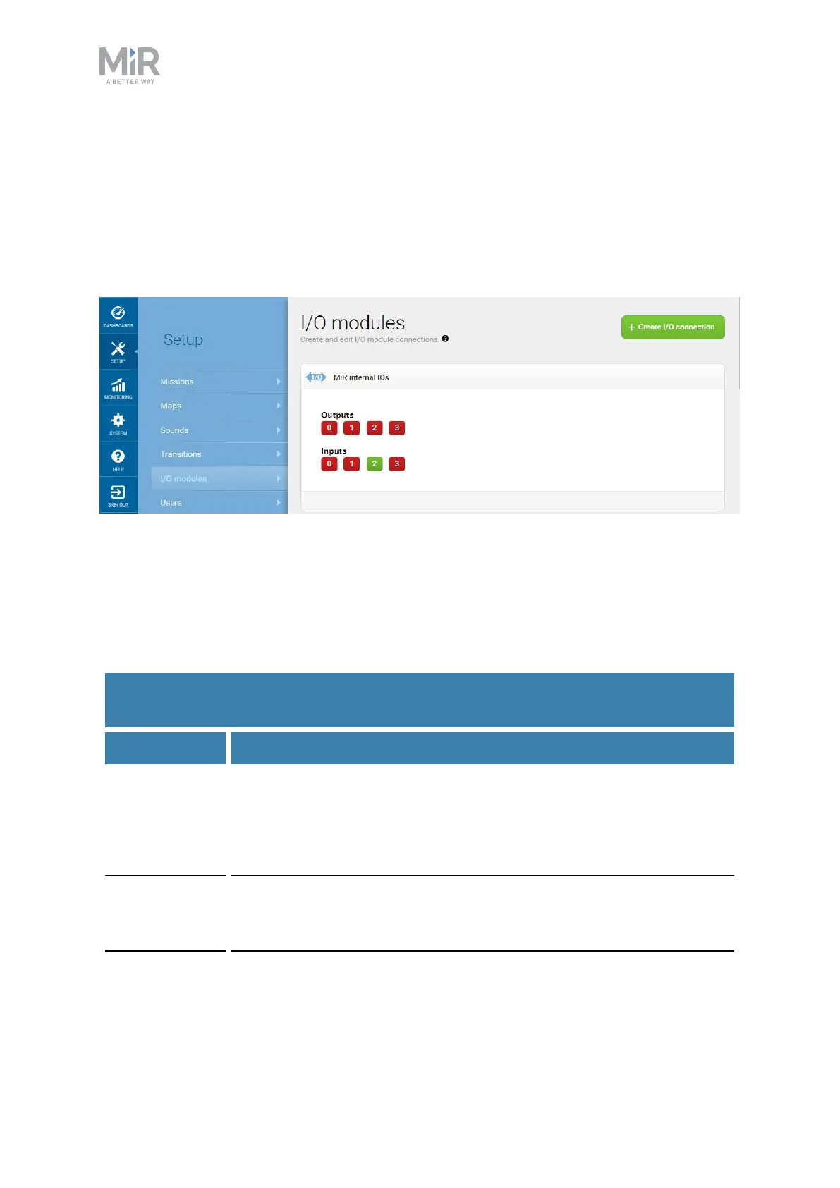
A top module can be connected to the output pins and monitor when they are
active at 24V. RTN is used as ground.
Inputs (I0, I1, I2, I3) can be used by the top application to send inputs to the
robot. When 24V is connected to the input pin, the robot registers the input as
active.
Figure 17.5. Example of I2 registered as high by the robot.
Output pins must be connected to RTN pins, and input pins must be connected
to 24V pins.
Table 17.2 contains the description of the pins of the GPIO interface.
Pin no. Description
1 Name: O0
Maximum current: 1A at 24 V
Standard function: Output 0
2 Name:RTN
Standard function: Protected return
Table 17.2.
Description of the pins in the GPIOinterface