17. Interface specifications
MiR1350 User Guide (en) 05/2022 - v.1.2 ©Copyright 2021-2022: Mobile Industrial Robots A/S. 254
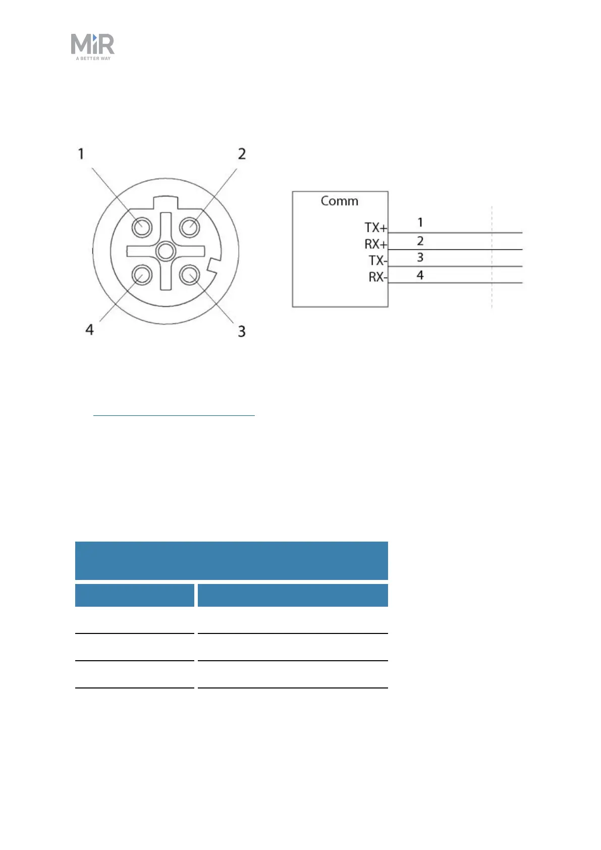
Ethernet
Figure 17.6. Ethernet connection. Pin numbers (left) and wiring diagram (right).
The communication interface is 10/100 Mbit Ethernet using a M12 connector—
see Connector list on page263.
The Ethernet connection supports power over Ethernet.
Various protocols are supported, such as Modbus. For more information on how
to use Modbus, ask your distributor for the guide How to use Modbus with
MiRrobots.
Table 17.3 contains the description of the pins of the Ethernet interface.
Pin no. Signal name
1 TX+
2 RX+
3 TX-
4 RX-
Table 17.3.
Description of the pins in the Ethernet interface