9
UTILITY OPERATION
9.4 MELSECNET/H Utility
9.4.7 Operating Target setting screen
9 - 131
9
UTILITY OPERATION
10
FUNCTIONS AND
PROGRAMMING
11
OVERVIEW OF
MULTIPLE CPU
SYSTEM
12
MULTIPLE CPU
SYSTEM
CONFIGURATION
13
MULTIPLE CPU
SYSTEM
CONCEPT
14
COMMUNICATIONS
BETWEEN CPU
MODULES
15
PARAMETERS
ADDED FOR
MULTIPLE CPU
16
PRECAUTIONS FOR
USE OF AnS SERIES
MODULE
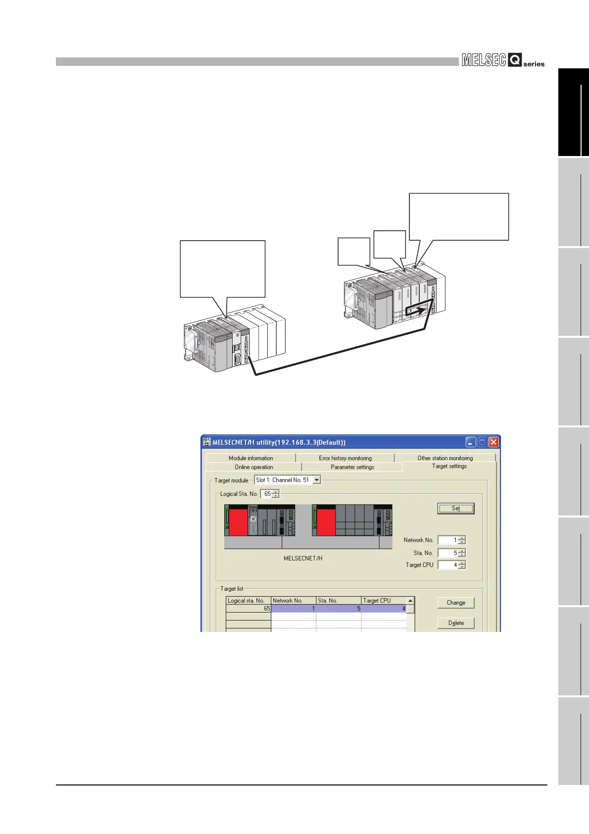
(1) Access example
Using the logical station No."65", access can be made from a MELSECNET/H module
controlled by the C Controller module to CPU No.4 via another MELSECNET/H
module (controlled by CPU No.2, network No.1).
From the Device monitor utility or user program (MELSEC data link function), access
can be made to CPU No.4 by opening Channel No.51 and specifying station No.65.
* 1 If the CPU No.4 cannot configure the multiple CPU system, access using the logical station
No.cannot be made to the CPU No.4.
The target setting for the above access is shown below.
Figure 9.97 System configuration
Figure 9.98 Target setting screen setting
Multiple CPU system
Control station
QJ71LP21G
1 Slot, Channel No.51
(Controlled by C
Controller module)
Normal station
QJ71LP21G
Station No.: 5
(Controlled by CPU No.2)
CPU
No.4
*1
Network No.1
CPU
No.2

 Loading...


